Kubota Ranger - Oregon
#31
 01-05-2015, 11:52 AM


#32
01-05-2015, 06:25 PM


#34
01-07-2015, 01:01 PM

http://s102.photobucket.com/user/flyinmonkeys32/media/20150106_173508_zpsb0b723a7.jpg.html
Also got a bunch of parts yesterday for the turbo and alternator oil drains, should be finishing the oil pan up this week and get the motor back in the truck for good
#35
01-18-2015, 01:15 AM
Got the oil pan finished up and on. Should have the motor back in a few days.
http://s102.photobucket.com/user/flyinmonkeys32/media/20150115_210242_zps19eeab0d.jpg.htmlhttp://s102.photobucket.com/user/flyinmonkeys32/media/20150115_210257_zpsd6fdb867.jpg.htmlhttp://s102.photobucket.com/user/flyinmonkeys32/media/20150115_210307_zps7b4b8491.jpg.htmlhttp://s102.photobucket.com/user/flyinmonkeys32/media/20150113_161347_zpsa9c7a7d0.jpg.html
http://s102.photobucket.com/user/flyinmonkeys32/media/20150115_210242_zps19eeab0d.jpg.htmlhttp://s102.photobucket.com/user/flyinmonkeys32/media/20150115_210257_zpsd6fdb867.jpg.htmlhttp://s102.photobucket.com/user/flyinmonkeys32/media/20150115_210307_zps7b4b8491.jpg.htmlhttp://s102.photobucket.com/user/flyinmonkeys32/media/20150113_161347_zpsa9c7a7d0.jpg.html
Last edited by flyinmonkeys32; 01-18-2015 at 01:27 AM.
#36
01-18-2015, 11:36 PM

Diesel Fan
#37
01-21-2015, 11:55 PM
I know enough about electronics to be dangerous. I am at the point where I am trying to do what Rangmar and I think a few others have done and use the factory crank trigger to get my tach reading.
I have the cluster out now and have traced the tach input path on that really thin circuit paper stuff. Is that where i should splice the sensor into the wire on the harness that goes to that lead? with one side of the sensor, and run the other side to ground? or do I need to peel that back thin circuit paper back and hook up to the actual PCB behind that? and is it that simple? any resistors or a rectifier inline?
On a different note, I have some time this weekend if you local guys still want to meet up?
#38
01-22-2015, 12:45 AM

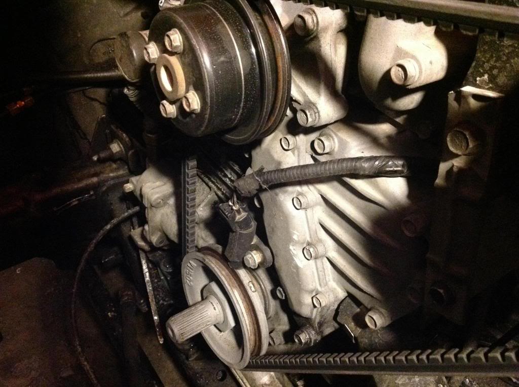
I ran a positive wire to a keyed on source to the crank sensor then the other wire on the crank sensor to the signal wire on the tach. Not the circuit board just the wire that connects to the correct pin. Make 2 notches in the crank pulley for a 4cyl truck and 3 for a 6cyl truck its just that easy
#39
01-22-2015, 08:05 AM

Diesel Fan
On my truck I used the factory crank sensor, one wire tied to 12 volt ignition and I found the tach wire in the engine harness. I know it was tan with a coloured stripe, I think a yellow stripe. Keeps it neater and it's one less wire you have to run through the firewall and beneath the dash
#40
01-22-2015, 07:46 PM
Diesel Fan


