
awarded


Site Sponsor

Joined: Apr 2009
Posts: 3,719
Likes: 636
From: Lexington SC
NV4500: General Information:
In 1992 Dodge and General Motors trucks started appearing in showrooms with one of the most versatile transmissions ever to be offered in a production truck: the New Venture Gear 4500. General Motors applications include it as an option in 3/4 and 1-ton full size trucks. Dodge standard duty units come in trucks with the 5.2 and 5.9 liter engine, while Dodge HD versions are used with Cummins diesels and V10�s.
This transmission is a fully synchronized (except reverse on GM models) five-speed gearbox with all of the strength and low-gear benefits (and then some) of the older granny four-speeds, with a 27-percent overdrive. The cast iron case is combined with massive gear sets in an almost compact 200lb package. This unit shifts with a smooth, short action and very distinct shift gates. We consider it the premium manual trans swap for 4x4 vehicles.
Gear Ratios:
Current production Dodge NV4500 and GM NV4500 share the same gear ratios. Early GM units (93-94) were built with a lower first gear ratio of 6.34 to 1.0. These low-geared GM boxes have since been discontinued and are generally much more difficult to obtain. We are able to provide new and remanufactured NV4500s with these early gearsets.
Beginning in 95�, all GM units were built with the same gear ratios as the Dodge unit.
GM 93-9495/up GM; 93/up DodgeFirst Gear6.345.61Second Gear3.443.04Third Gear1.711.67Fourth Gear1.001.00Fifth Gear0.730.73Reverse6.345.61
SpecificationsGM 93-9495/up GM; 93/up DodgeFirst Gear6.345.61Second Gear3.443.04Third Gear1.711.67Fourth Gear1.001.00Fifth Gear0.730.73Reverse6.345.61
Dry weight:195 lbs.Oil capacity:1 gallonRated GVW:14,500 lbs.Case material:cast ironSynchronizers:Carbon fiber compositeMain/Counter shaft bearings:Timken tapered roller
DimensionsNV4500GM (6.34)GM (5.61)DodgeDodge HDMain case12.375"12.375"12.375"12.375"4WD Adapter Housing8.1258.1256.256.252WD Tailhousing6" Tailhousing6" Tailhousing13" Tailhousing13" TailhousingYokeFixed YokeFixed Yoke30 spl Slip yoke31 spl Slip yokeInput shaft stickout6.6256.6257.6257.625Input shaft spline1.125" 10spl1.125" 10spl1.125" 10spl1.250" 10splPilot Dia.590".590".750".750"
Bearing Retainer specification
BellhousingT/O bearingIndex Dia.Snout Dia.GM NV4500 1993-955.125"1.373"GM NV4500 1996 and up5.60"none: Int Slave CylDodge NV4500 Standard Duty5.60"1.43"Dodge NV4500 Heavy Duty5.60"1.75Bellhousing Bolt Pattern:
- GM 1993-1995 10.078 across the top, 10.394 across the bottom, 4.685 vertically
- GM 1996 + up 10.078 across the top, 9.738 across the bottom, 6.043 vertically
- Dodge (All) 10.078 across the top, 9.738 across the bottom, 6.043 vertically
The NV4500 shifter will have a short stub sticking up from the top cover, There are 3 different methods by which a shifter extension handle attaches:
- Dodge NV4500 1993-1999 A short, square stub sticks up
- Dodge NV4500 1999-up Threaded stub, 14mm x 1.5 pitch threads
- GM NV4500 (All) Threaded stub, 12mm x 2.0 pitch threads
You MUST use the correct synthetic lubricant. The GM part no. for the correct oil is 12346190 (quart). The Dodge part number for the same oil is 4874459 Use of ANY other oil in the NV4500 will lead to failure and also voids any chance of a warranty claim.
---AutoMerged DoublePost---
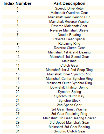
Don't mind the wavy numbers in the index it was being a bitch

Diesel Enthusiast
Joined: Apr 2007
Posts: 272
Likes: 11
From: Leduc, Alberta, Cana
(Please note, I did not mention any steps for painting. I did not have to paint my panels, I got lucky and paint matched paint codes for my parts. Paint code is in your glovebox tag)
I went around and swapped my head lights from the 03-05 style to the 06 up recently. It really wasnt too hard and can be done in your driveway/garage, etc with basic hand tools. One tool most people dont have is an antenna wrench

You will need 06 up head lights and fenders as well as a front bumper. If you get your head lights from a wrecker, ask for the 3 headlight pigtals for each light. Otherwise you will have to find some somewhere. I had an ARB winch bumper already, and picked up my headlights and fenders off KIJIJI for $500 with the pigtails.
Start by opening you hood, disconnecting you batteries.

Next you will have to remove any accessories you have on your fenders, extra antennas/fender flares/mud flaps/etc


Test fitting flare and checking color match

Next, remove your headlight, 2 10mm bolts on the inside by the grill, and one under the headlight at the bottem of the fender. The headlight will still be held in with one last mount which can be popped out by prying with slight pressure. There are 2 plugs on the back of the headlight to be unplugged from the bulbs

Next is the fender to be removed, on the passenger side, you have to remove the antenna and mast which is were the fancy wrench comes in handy.
The fender is held in place by 10mm bolts, and the cowl vent pannel has to be removed to get the 2 hidden ones. There is also the 10mm bolts across the top of the fender, 2 below where the headlight sat, one at the bottem rocker behind the tire, and another which you need to get the inner fender off to access it about where the factory molding points to. Carefully remove the fender now. Truck should now look like this:

Its time to do the wiring, you have 2 factory plugs on your truck, and 3 for the new lights, what do you do now? If you notice, the factoy lights and your new pigtails have the same color code. Just snip them and splice them back together. For the second park light/signal light pigtail, it is the same as the original signal light wiring and you just spice it into that plug
Notice the white wire with yellow tracer, this is the signal light wiring for the left side


Be sure to leave a few inches of wiring to on the second signal light pigtail to allow it to reach the bulb, here is my finished harness


Now your ready for reassembly. On the passenger side, there is a black plastic air deflector which needs to be removed to fit the new lights. Also remember to reinstall the antenna and mast. Fender goes on first, same way it came off, followed by the headlight. Leave everything loose to allow body gaps be adjusted and lined up.

Once everything is lined up and straight, then proceed to tighten everything up. Reinstall any accessories you had.

The driver and passenger side are fairly similar to do other than the mentioned air deflector and antenna on the passenger side. With this completed, you will not have the signal light "wink" the new trucks have, when signaling, the head light turns off. That is part of the programming for the body control module.
It took me about 2 hours to complete this, with air tools. When finished remember to realign your headlights.
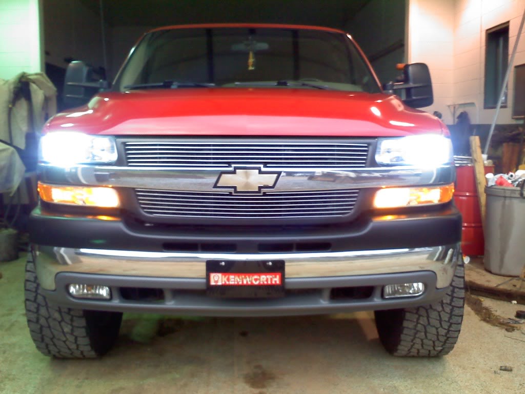
Enjoy your new looking truck!

I went around and swapped my head lights from the 03-05 style to the 06 up recently. It really wasnt too hard and can be done in your driveway/garage, etc with basic hand tools. One tool most people dont have is an antenna wrench
You will need 06 up head lights and fenders as well as a front bumper. If you get your head lights from a wrecker, ask for the 3 headlight pigtals for each light. Otherwise you will have to find some somewhere. I had an ARB winch bumper already, and picked up my headlights and fenders off KIJIJI for $500 with the pigtails.
Start by opening you hood, disconnecting you batteries.
Next you will have to remove any accessories you have on your fenders, extra antennas/fender flares/mud flaps/etc
Test fitting flare and checking color match
Next, remove your headlight, 2 10mm bolts on the inside by the grill, and one under the headlight at the bottem of the fender. The headlight will still be held in with one last mount which can be popped out by prying with slight pressure. There are 2 plugs on the back of the headlight to be unplugged from the bulbs
Next is the fender to be removed, on the passenger side, you have to remove the antenna and mast which is were the fancy wrench comes in handy.
The fender is held in place by 10mm bolts, and the cowl vent pannel has to be removed to get the 2 hidden ones. There is also the 10mm bolts across the top of the fender, 2 below where the headlight sat, one at the bottem rocker behind the tire, and another which you need to get the inner fender off to access it about where the factory molding points to. Carefully remove the fender now. Truck should now look like this:
Its time to do the wiring, you have 2 factory plugs on your truck, and 3 for the new lights, what do you do now? If you notice, the factoy lights and your new pigtails have the same color code. Just snip them and splice them back together. For the second park light/signal light pigtail, it is the same as the original signal light wiring and you just spice it into that plug
Notice the white wire with yellow tracer, this is the signal light wiring for the left side
Be sure to leave a few inches of wiring to on the second signal light pigtail to allow it to reach the bulb, here is my finished harness
Now your ready for reassembly. On the passenger side, there is a black plastic air deflector which needs to be removed to fit the new lights. Also remember to reinstall the antenna and mast. Fender goes on first, same way it came off, followed by the headlight. Leave everything loose to allow body gaps be adjusted and lined up.
Once everything is lined up and straight, then proceed to tighten everything up. Reinstall any accessories you had.
The driver and passenger side are fairly similar to do other than the mentioned air deflector and antenna on the passenger side. With this completed, you will not have the signal light "wink" the new trucks have, when signaling, the head light turns off. That is part of the programming for the body control module.
It took me about 2 hours to complete this, with air tools. When finished remember to realign your headlights.
Enjoy your new looking truck!
Diesel Enthusiast
Joined: May 2009
Posts: 211
Likes: 11
From: North Carolina
Requirements-
One 200v-1A Diode
Common Sense.
If you would like to have your DRLs to stay on with your low beams and fog lamps, than this is for you!
First, take out your highlight relay and DRL relay. Look for the 87 pin on each relay. Take your 200v-1A diode and take the anode side and stick the end into the 87 pin hole where the Headlight Relay was. Then take the cathode end and stick it into the DRL relay 87 pin hole. Make sure that the diode is not touching any other metals or fuses. Take the relays and place them back in, might need to push a little harder because of the diode. And TA-DA!

The EASY way!
For many years I have been a big fan of connectors like these "piggy backs"


Really simple if you have a spare port on your fuse block. What if you don't have a spare, or if you need more than what the fuse block can supply. Well people, I have found just what a person needs!!


This can be used ANYWHERE! It simply plugs into your fuse block at any location. With reference to the pictures above, the red fuse is for the circuit you tapped into. The blue fuse is for the pigtail and whatever you are powering. Best part of all of this, I only paid $6 for the ATM (Mini) version. The ATC (Auto) style is a little steeper, coming in at $15.
Hunting for power, or splicing into wires is a thing of the past! Here it is in a 2001 Dodge RAM, cab fuse block;

They are called Tapa-Circuit's. I bought mine at a local electronics shop, Ko-Hen. This is a link to WirthCo's site, the manufactures.
Tapa-Circuit� - Wirthco Engineering, Inc.
For many years I have been a big fan of connectors like these "piggy backs"


Really simple if you have a spare port on your fuse block. What if you don't have a spare, or if you need more than what the fuse block can supply. Well people, I have found just what a person needs!!


This can be used ANYWHERE!
It simply plugs into your fuse block at any location. With reference to the pictures above, the red fuse is for the circuit you tapped into. The blue fuse is for the pigtail and whatever you are powering. Best part of all of this, I only paid $6 for the ATM (Mini) version. The ATC (Auto) style is a little steeper, coming in at $15. Hunting for power, or splicing into wires is a thing of the past! Here it is in a 2001 Dodge RAM, cab fuse block;

They are called Tapa-Circuit's. I bought mine at a local electronics shop, Ko-Hen. This is a link to WirthCo's site, the manufactures.
Tapa-Circuit� - Wirthco Engineering, Inc.
Hey All,
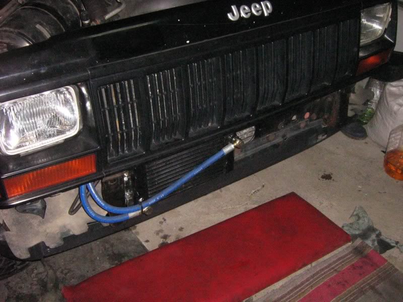
I had thought there was something a little off with my boost here lately. I searched all over different forums and found alot of answers and pictures of these homemade boost leak testers. To be honest, I just did not have the time to drive around and peice one of these together. So I ordered one from a place called turboboostleaktesters.com. It cost like 36 dollars for the tester and shipping was like an additional 10 bones.
Here I have it hooked up. I had the choice of either an air hose fitting or a tire valve stem. I just choose the tire valve stem for my preference.

And with just 5 psi and some soapy water found a leak.

Was able to get the leak fixed and check the entire system. Really if a person does not have the time or limited on stores that may carry the stuff needed local, this is a good option. I wish I would have found this a couple years back. Just thought I would share it with you.
oudive
I had thought there was something a little off with my boost here lately. I searched all over different forums and found alot of answers and pictures of these homemade boost leak testers. To be honest, I just did not have the time to drive around and peice one of these together. So I ordered one from a place called turboboostleaktesters.com. It cost like 36 dollars for the tester and shipping was like an additional 10 bones.
Here I have it hooked up. I had the choice of either an air hose fitting or a tire valve stem. I just choose the tire valve stem for my preference.
And with just 5 psi and some soapy water found a leak.
Was able to get the leak fixed and check the entire system. Really if a person does not have the time or limited on stores that may carry the stuff needed local, this is a good option. I wish I would have found this a couple years back. Just thought I would share it with you.
oudive

Site Sponsor - Alligator Performance
Joined: Sep 2010
Posts: 126
Likes: 20
From: Post Falls Idaho
Alligator Performance Installs H&S Performance Intake Elbow On 2010 Cummins
Here at Alligator Performance we know that most people buying performance parts do not have fancy shops and specialty tools to get most installs done. So we did this tech article driveway style. We used easy to find hand tools and we will cover some of the issues you will encounter doing this install yourself and what tools are needed to get it done quickly.

Here you can see that we have the stock intake elbow in place with the H&S EGR delete plates in place. First thing you will need to do is remove the dip stick bracket with a 10mm socket.

Next you will need to remove the 6 - 10mm bolts holding the intake elbow onto the intake tray. You will need to pull the vent tube out of the side of the valve cover to get to the back corner bolt. Then we moved on to the intercooler pipe.

This is a 7/16� nut on the intercooler boot clamp, you will need to loosen the nut until it is almost all the way off in order to get the boot of the beaded lip on the intake elbow. You may notice that the intake elbow does not just pull out of the boot even after the clamp is removed. Just give the elbow a twist and you will hear the intercooler boot break loose, the rubber usually binds to the metal.

The last thing to do is remove the wiring harness tabs from the front and back of the intake elbow. The harness on the back is easy to remove it is only held on by a 10mm bolt. The one on the front pictured above is a little trickier. You can see in the picture that we had to pry the plastic tab out with a small flathead screw driver in order to pull it off of the stud.

Now you can see that everything is freed up and we are ready to remove the factory intake elbow. It may not move right away as the gasket between the intake elbow and the intake tray acts as an adhesive. Just push down in the curved part of the intake elbow to break it loose.

Here you can see the elbow removed and the new gasket in place.

Here you can see the major differences between the factory unit and H&S�s much sleeker and freer flowing design.

Here you can see the actual opening deference between the two elbows. The H&S has a smooth finish inside instead of a rough cast surface like the factory unit and the opening is 5/8� wider than the factory elbow.

H&S was also able to increase air flow by utilizing a large inlet were the intercooler pipe connects to it also removing the factory butterfly valve for the EGR frees up extra air flow.

We did not do the upgraded intercooler pipe just yet so we can show those of you who decide not to buy the intercooler pipe what you will encounter when doing this install.
On the factory intercooler pipe there is one clamp the can�t be removed so you will have to cut it off with a die grinder. Be very careful not to grind all the way through into the pipe as you could cause a boost leak or a weak spot in the pipe. We ground through the clamp ring until we could see the metal getting thin and then we slid a flathead screw driver under it and snapped it the rest of the way through.

Once we had the factory clamp removed we installed the boot provided by H&S. This boot at first glance appeared way to small, but with a little work we got it on and you will see that it fits perfectly once it is past the bead molded into the plastic factory pipe.

Here you can see we have the intercooler pipe back in place as well as the new H&S intake elbow. Also notice the replacement dip stick bracket. It mounts under the two front 8mm bolts holding on the plastic valve cover shield. Then we used the 11mm nut and bolt provided in the kit to attach the dip stick to the new bracket.

The last thing you will have to do is relocate the MAS air flow sensor to the back side of the H&S Intake Elbow.

Here is the finished product! You can immediately see how much cleaner the engine bay looks and the increased air flow will result in better throttle response and a noticeable drop in the EGT�s
Here at Alligator Performance we know that most people buying performance parts do not have fancy shops and specialty tools to get most installs done. So we did this tech article driveway style. We used easy to find hand tools and we will cover some of the issues you will encounter doing this install yourself and what tools are needed to get it done quickly.
Here you can see that we have the stock intake elbow in place with the H&S EGR delete plates in place. First thing you will need to do is remove the dip stick bracket with a 10mm socket.
Next you will need to remove the 6 - 10mm bolts holding the intake elbow onto the intake tray. You will need to pull the vent tube out of the side of the valve cover to get to the back corner bolt. Then we moved on to the intercooler pipe.
This is a 7/16� nut on the intercooler boot clamp, you will need to loosen the nut until it is almost all the way off in order to get the boot of the beaded lip on the intake elbow. You may notice that the intake elbow does not just pull out of the boot even after the clamp is removed. Just give the elbow a twist and you will hear the intercooler boot break loose, the rubber usually binds to the metal.
The last thing to do is remove the wiring harness tabs from the front and back of the intake elbow. The harness on the back is easy to remove it is only held on by a 10mm bolt. The one on the front pictured above is a little trickier. You can see in the picture that we had to pry the plastic tab out with a small flathead screw driver in order to pull it off of the stud.
Now you can see that everything is freed up and we are ready to remove the factory intake elbow. It may not move right away as the gasket between the intake elbow and the intake tray acts as an adhesive. Just push down in the curved part of the intake elbow to break it loose.
Here you can see the elbow removed and the new gasket in place.
Here you can see the major differences between the factory unit and H&S�s much sleeker and freer flowing design.
Here you can see the actual opening deference between the two elbows. The H&S has a smooth finish inside instead of a rough cast surface like the factory unit and the opening is 5/8� wider than the factory elbow.
H&S was also able to increase air flow by utilizing a large inlet were the intercooler pipe connects to it also removing the factory butterfly valve for the EGR frees up extra air flow.
We did not do the upgraded intercooler pipe just yet so we can show those of you who decide not to buy the intercooler pipe what you will encounter when doing this install.
On the factory intercooler pipe there is one clamp the can�t be removed so you will have to cut it off with a die grinder. Be very careful not to grind all the way through into the pipe as you could cause a boost leak or a weak spot in the pipe. We ground through the clamp ring until we could see the metal getting thin and then we slid a flathead screw driver under it and snapped it the rest of the way through.
Once we had the factory clamp removed we installed the boot provided by H&S. This boot at first glance appeared way to small, but with a little work we got it on and you will see that it fits perfectly once it is past the bead molded into the plastic factory pipe.
Here you can see we have the intercooler pipe back in place as well as the new H&S intake elbow. Also notice the replacement dip stick bracket. It mounts under the two front 8mm bolts holding on the plastic valve cover shield. Then we used the 11mm nut and bolt provided in the kit to attach the dip stick to the new bracket.
The last thing you will have to do is relocate the MAS air flow sensor to the back side of the H&S Intake Elbow.
Here is the finished product! You can immediately see how much cleaner the engine bay looks and the increased air flow will result in better throttle response and a noticeable drop in the EGT�s
Site Sponsor - Alligator Performance
Joined: Sep 2010
Posts: 126
Likes: 20
From: Post Falls Idaho
I know this has been covered before on many different forums. But I am in the mood to do tech articles tonight and I really appreciate this site for the number of extremely helpful people we have here. I would like to give back to this awesome community by sharing some of the knowledge I have gained in the diesel industry over the years.
As some may know if you install the pickup tube provided with the Air Dog pumps the way they specify in their instructions you will have issues with the pickup tube swinging around in the tank causing the truck to run out of fuel once you get to a quarter of a tank going around sharp corners. Here is my personal fix for this problem that I have been doing for years.
First I drop the tank and clean all of the dirt from around the sending unit so that once the sending unit is removed the dirt can not fall into the tank. Here are my before and after pictures I took of a truck we worked on Saturday.


Once the sending unit is clean you can use a large flathead screw driver and a hammer to pound the lock ring counter clock wise. This will allow the sending unit to be lifted out of the tank. Be very careful not to yank it out as you can bend the float arm that reads fuel level.


Once you have the sending unit out and on the bench you will notice there is a honey comb pattern molded into the plastic top. There is also the factory supply elbow which is also molded into the top of the sending unit. We no longer need this fitting since the Air Dog will be getting it's supply from the new pickup tube. I grind off this elbow as well as some of the webbing around it to make room for the black rubber grommet that the pickup tube slides into.


Once you have the grommet installed you are ready to cut the pickup tube to length and install it through the grommet. If you are working on an 05 or newer Cummins you can remove the factory lift pump from the bowl at the bottom of the sending unit. I use a pair of large dykes to cut the plastic fingers holding it in place. Measure from the top of the fuel tank to the bottom to get the length of your pickup tube. Don't forget to take into account the thickness of the bottom of the sending unit.


Once you cut the pickup tube to your required length either make a groove in either side or cut it at an angle so the pickup can not suction it'self to the bottom of the sending unit.

I also drill 5 5/8" holes as close as I can to the bottom of the bowl to allow fuel to fill the bowl up as fast as possible. The factory sending unit has a very restrictive mesh that allows fuel to slowly trickle through from the bottom filling the bowl. This slow trickle is fine for supplying the little factory lift pump. But the Air Dog moves so much volume that it will suck the bowl dry instantly without drilling holes in the sides of the bowl. Do not drill the holes directly in the bottom of the sending unit. This will allow the Air Dog to suck up large amounts of sediment that can pool up at the bottom of the tank. The mesh will keep the dirt out of the bowl.

Now you can install the pickup tube into the sending unit and make sure everything lines up good and the sending unit fits properly into the tank.

At this point I revert back to the Air Dog instructions to complete the rest of the install. I hope this helps someone else out as much as it has helped us to reduce issues with our customers trucks.
As some may know if you install the pickup tube provided with the Air Dog pumps the way they specify in their instructions you will have issues with the pickup tube swinging around in the tank causing the truck to run out of fuel once you get to a quarter of a tank going around sharp corners. Here is my personal fix for this problem that I have been doing for years.
First I drop the tank and clean all of the dirt from around the sending unit so that once the sending unit is removed the dirt can not fall into the tank. Here are my before and after pictures I took of a truck we worked on Saturday.
Once the sending unit is clean you can use a large flathead screw driver and a hammer to pound the lock ring counter clock wise. This will allow the sending unit to be lifted out of the tank. Be very careful not to yank it out as you can bend the float arm that reads fuel level.
Once you have the sending unit out and on the bench you will notice there is a honey comb pattern molded into the plastic top. There is also the factory supply elbow which is also molded into the top of the sending unit. We no longer need this fitting since the Air Dog will be getting it's supply from the new pickup tube. I grind off this elbow as well as some of the webbing around it to make room for the black rubber grommet that the pickup tube slides into.
Once you have the grommet installed you are ready to cut the pickup tube to length and install it through the grommet. If you are working on an 05 or newer Cummins you can remove the factory lift pump from the bowl at the bottom of the sending unit. I use a pair of large dykes to cut the plastic fingers holding it in place. Measure from the top of the fuel tank to the bottom to get the length of your pickup tube. Don't forget to take into account the thickness of the bottom of the sending unit.
Once you cut the pickup tube to your required length either make a groove in either side or cut it at an angle so the pickup can not suction it'self to the bottom of the sending unit.
I also drill 5 5/8" holes as close as I can to the bottom of the bowl to allow fuel to fill the bowl up as fast as possible. The factory sending unit has a very restrictive mesh that allows fuel to slowly trickle through from the bottom filling the bowl. This slow trickle is fine for supplying the little factory lift pump. But the Air Dog moves so much volume that it will suck the bowl dry instantly without drilling holes in the sides of the bowl. Do not drill the holes directly in the bottom of the sending unit. This will allow the Air Dog to suck up large amounts of sediment that can pool up at the bottom of the tank. The mesh will keep the dirt out of the bowl.
Now you can install the pickup tube into the sending unit and make sure everything lines up good and the sending unit fits properly into the tank.
At this point I revert back to the Air Dog instructions to complete the rest of the install. I hope this helps someone else out as much as it has helped us to reduce issues with our customers trucks.
Last edited by Alligator Vinny; Nov 11, 2010 at 07:28 PM.


Diesel Fan
Joined: Oct 2009
Posts: 11
Likes: 0
TRUCK DOES NOT LIKE TO FREE REV AT ALL! IS FINE UNDER A LOAD. IS THIS CONSIDERED A NORMAL CONDITION WITH THE PISTON/INJECTOR/GOVERNOR COMBO I AM RUNNING?
THE TIMING IS SET AT 17 DEGREES NOW. I HAVE HEAD STUDS, O-RINGS, AND MARINE PISTONS SO I AM CONSIDERING INCREASING TIMING- HOW HIGH SHOULD I GO AND WHAT BENEFITS WILL I SEE. IT DOSENT SEEM TO HAVE ANY USABLE POWER FROM 3000 TO 4000 RPMS. ALSO CONSIDERED NORMAL??
THE TIMING IS SET AT 17 DEGREES NOW. I HAVE HEAD STUDS, O-RINGS, AND MARINE PISTONS SO I AM CONSIDERING INCREASING TIMING- HOW HIGH SHOULD I GO AND WHAT BENEFITS WILL I SEE. IT DOSENT SEEM TO HAVE ANY USABLE POWER FROM 3000 TO 4000 RPMS. ALSO CONSIDERED NORMAL??
Diesel Enthusiast
Joined: Aug 2010
Posts: 98
Likes: 10
From: Transylvania
Finally got around to installing my custom oil cooler, after close to 6 months of gathering parts.
Cooler installed behind the bumper:
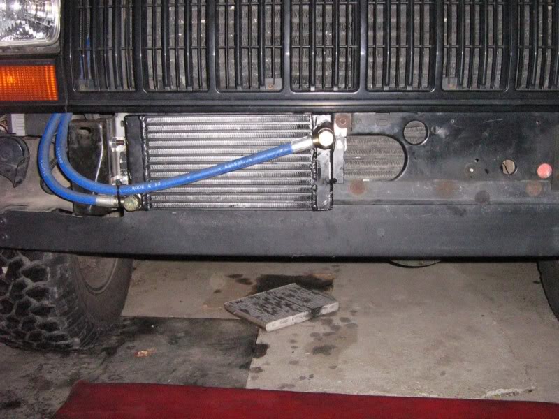
No pics with the bumper on because nothing is visible. The bumper needs some sort of vents for extra airflow.
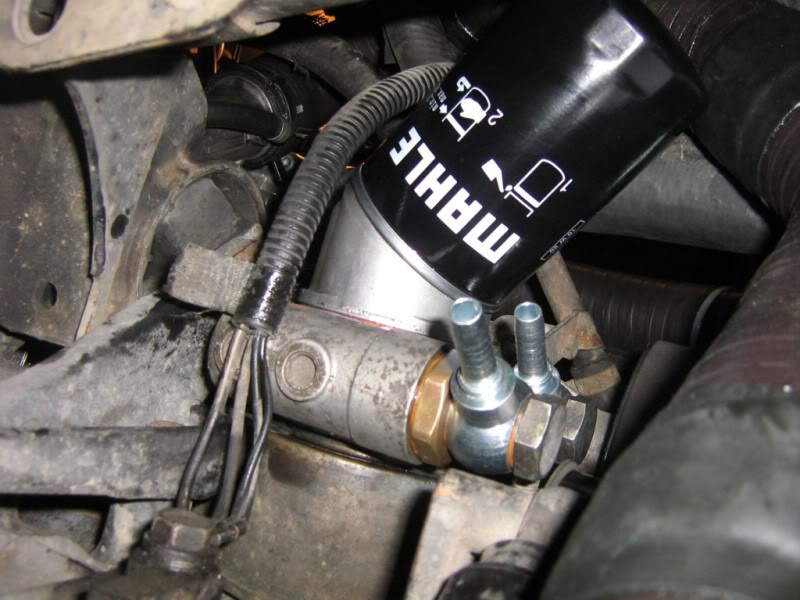
Oil thermostat over the stock water-oil cooler, from underneath:
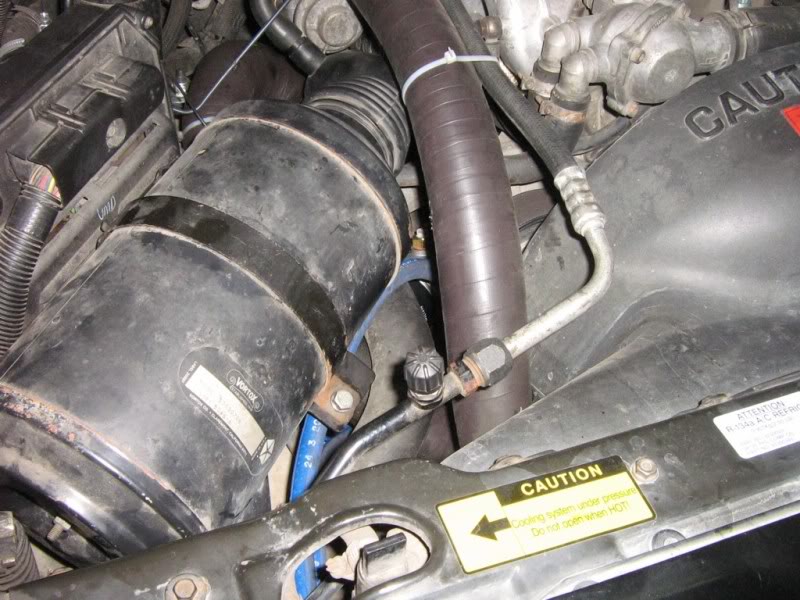
Almost invisible from under the hood:
At the same time I installed an oil temperature gauge and here is where things have me wondering..
Normal driving, with some long hills, 30F outside temperature I only saw oil temperatures up to 160-170F, water temperature is at around 200F and my oil thermostat opens around 200F. I feel stupid because I never got around to measuring without the extra oil cooler...
Could the oil be apparently too cold because of the cold day outside ? Oil pressure was in the normal range and the oil cooler was cold to touch, so the thermostat was closed.
Cooler installed behind the bumper:
No pics with the bumper on because nothing is visible. The bumper needs some sort of vents for extra airflow.
Oil thermostat over the stock water-oil cooler, from underneath:
Almost invisible from under the hood:
At the same time I installed an oil temperature gauge and here is where things have me wondering..
Normal driving, with some long hills, 30F outside temperature I only saw oil temperatures up to 160-170F, water temperature is at around 200F and my oil thermostat opens around 200F. I feel stupid because I never got around to measuring without the extra oil cooler...
Could the oil be apparently too cold because of the cold day outside ? Oil pressure was in the normal range and the oil cooler was cold to touch, so the thermostat was closed.
Last edited by AdrianD; Dec 11, 2010 at 12:33 PM.


