
59 Chevy/Cummins


Thread Starter
|
Diesel Fan
Joined: Jul 2012
Posts: 11
Likes: 1
I just ran across this forum and after reading about some of the projects that are posted here, I thought you might like to see one of mine.
I started this project a while ago and took lots of photos as it went along.
I'll split them up into a few post so they stay within the photo limit of the forum.
.................................................. .................................................. ...................
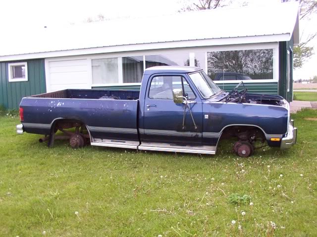
This old 59 Chevy truck has been my main transportation during the summer months since 1995.
It started out with the cab set on a mid 70's half ton chassis with a 350 and 400 turbo transmission.
Four years ago I up graded to a 85 Chevy 1-ton and a 6.2 diesel ( non turbo ).
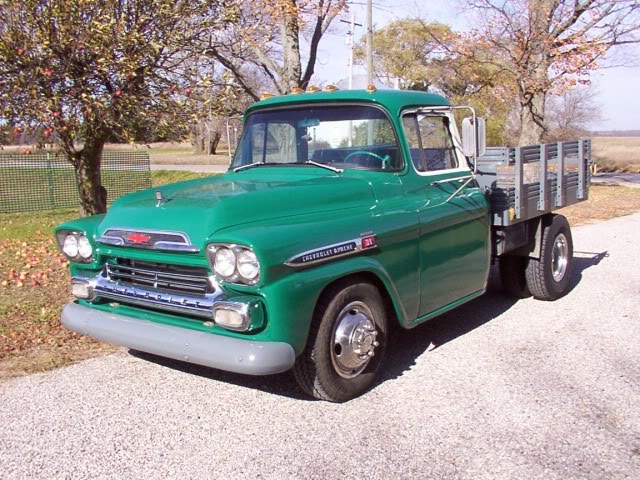
I display at antique tractor shows during the summer and the 6.2 has a hard time hauling my gooseneck trailer loaded with tractors up some of the hills around here.
A couple of months ago, my 87 year old uncle decided that it was getting to be too much work hauling his tractors to shows so he decided to quit showing and sell everything off.
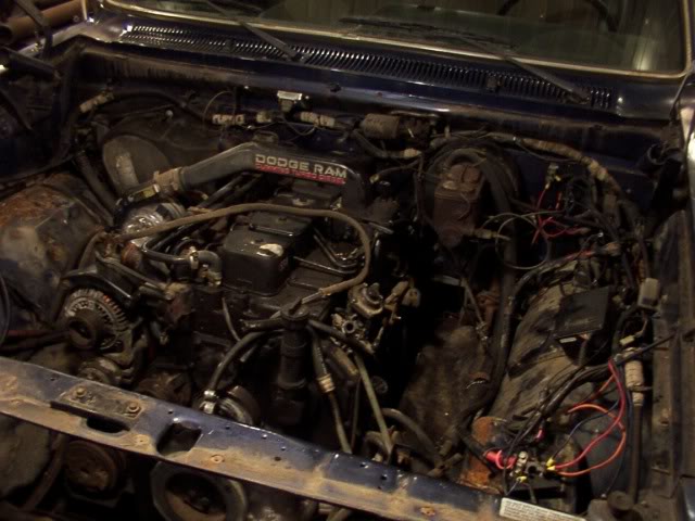
I had told him that if he ever sold his Dodge, I would like to have it to put the engine in my 59 so he offered me his truck.
The Dodge currently has less than 91,000 miles on it.
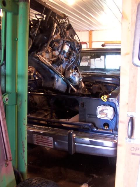
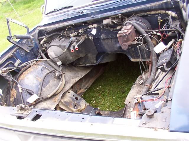
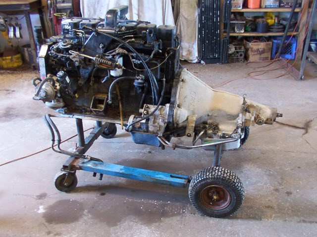
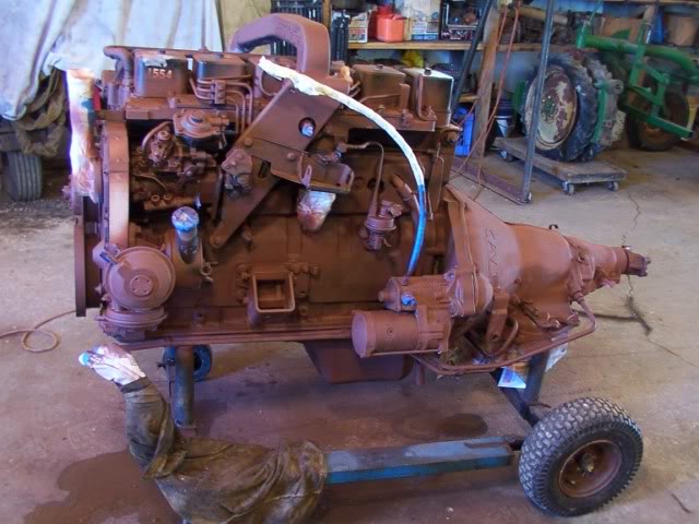
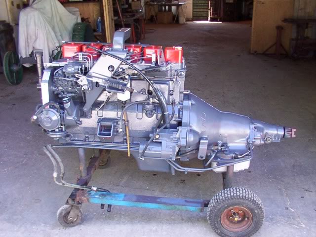
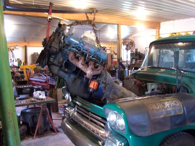
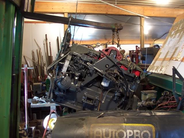
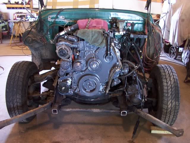
The exhaust and all the wires and hoses are removed and the engine is ready to lift out of the Dodge.
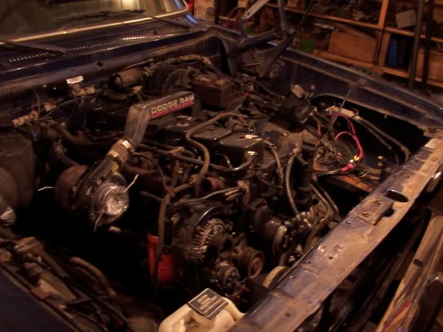
Here she comes up and over the radiator support.
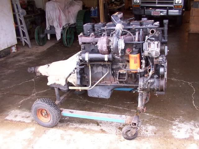
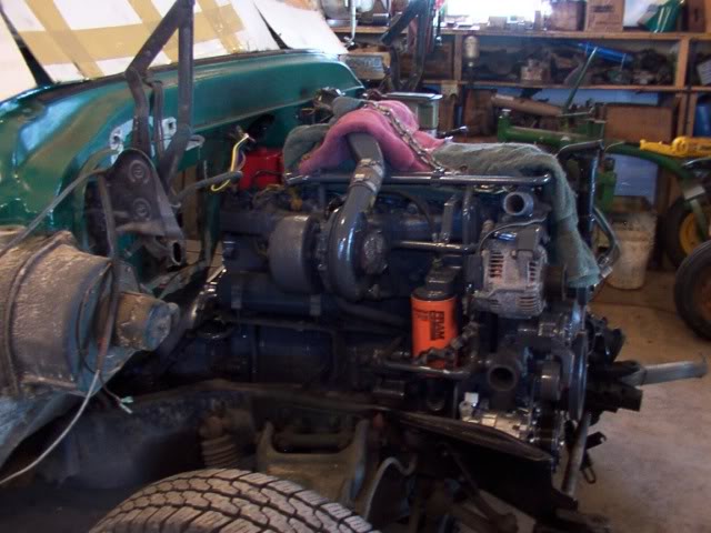
Setting down on the stand so it can be cleaned up and painted.
There are plastic bags fastened over both ends of the turbo so nothing gets into it.
The rear crankshaft seal looks like it has been leaking a little so that is getting replaced now.
While the transmission is off, I'm going to replace the trans filter and both seals.
I'm also removing the timing gear cover and make a locking tab for that dowel pin that has worked loose on some engines.
The front crankshaft seal will get replaced before I re-install the gear cover.
The water pump isn't leaking but I'm going to put on a new one anyway simply because this one is 22 years old.
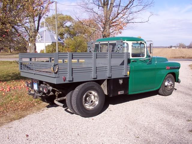
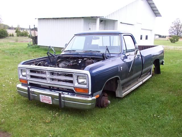
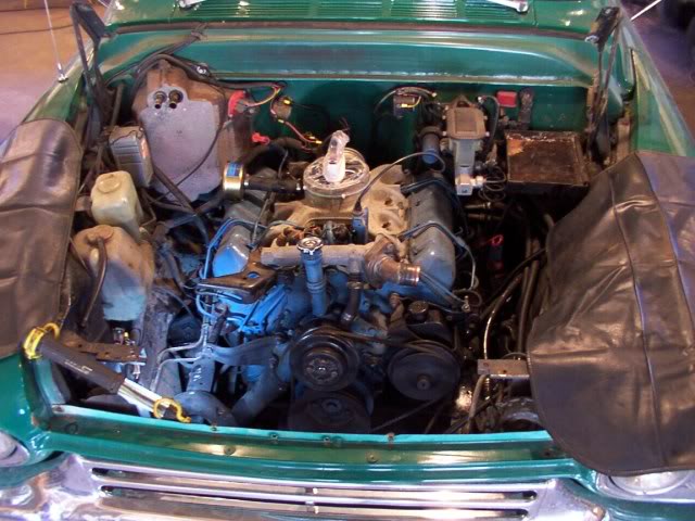
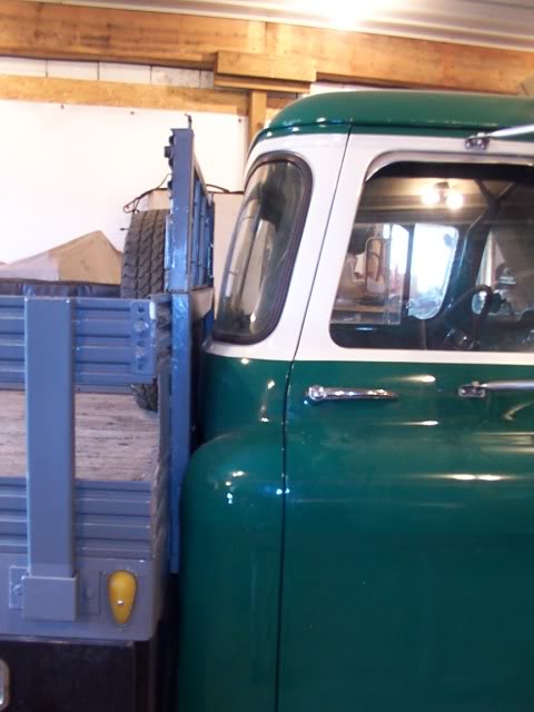
Here are some photos of the Dodge.
He just put new tires on it a couple of years ago and has only put about 300 miles on them and they have a load range-E rating.
The tires on the back of my truck are a load range-D so I'm going to have the tires off the Dodge put onto the rear of my truck.
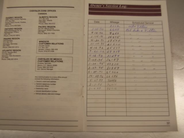
I'm looking the paperwork that came with the truck and ran across and interesting item.
In the back of the warranty book is a record of oil changes at 3,000 mile intervals from 1990 to 1999.
The last mileage is listed at 82,416 and the speedometer shows 90,708 miles on it now.
From August of 1999 to now, the truck has only been driven 8,292 miles and most of that was to and from the tractor shows in the summer.
He said that he hadn't driven it in the winter since the mid 90's so that explains why the body isn't rusted out.
Pulled the torque converter and put in a new front pump seal on the transmission.
Then I stood it up and pulled the pan off to change the filter.
The old filter doesn't look bad at all with just a small sludge spot on it.
I couldn't see any metal grit in the pan so I was happy with that.

I'm using a deeper aluminum pan so the new filter has a spacer so it sits down farther into the pan.

The new pan is all bolted in place.
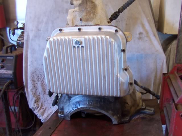
The transmission is then mounted back up to the engine.
The last thing left to do is to fix that dowel pin inside the timing gear case.
I started this project a while ago and took lots of photos as it went along.
I'll split them up into a few post so they stay within the photo limit of the forum.
.................................................. .................................................. ...................
This old 59 Chevy truck has been my main transportation during the summer months since 1995.
It started out with the cab set on a mid 70's half ton chassis with a 350 and 400 turbo transmission.
Four years ago I up graded to a 85 Chevy 1-ton and a 6.2 diesel ( non turbo ).
I display at antique tractor shows during the summer and the 6.2 has a hard time hauling my gooseneck trailer loaded with tractors up some of the hills around here.
A couple of months ago, my 87 year old uncle decided that it was getting to be too much work hauling his tractors to shows so he decided to quit showing and sell everything off.
I had told him that if he ever sold his Dodge, I would like to have it to put the engine in my 59 so he offered me his truck.
The Dodge currently has less than 91,000 miles on it.
The exhaust and all the wires and hoses are removed and the engine is ready to lift out of the Dodge.
Here she comes up and over the radiator support.
Setting down on the stand so it can be cleaned up and painted.
There are plastic bags fastened over both ends of the turbo so nothing gets into it.
The rear crankshaft seal looks like it has been leaking a little so that is getting replaced now.
While the transmission is off, I'm going to replace the trans filter and both seals.
I'm also removing the timing gear cover and make a locking tab for that dowel pin that has worked loose on some engines.
The front crankshaft seal will get replaced before I re-install the gear cover.
The water pump isn't leaking but I'm going to put on a new one anyway simply because this one is 22 years old.
Here are some photos of the Dodge.
He just put new tires on it a couple of years ago and has only put about 300 miles on them and they have a load range-E rating.
The tires on the back of my truck are a load range-D so I'm going to have the tires off the Dodge put onto the rear of my truck.
I'm looking the paperwork that came with the truck and ran across and interesting item.
In the back of the warranty book is a record of oil changes at 3,000 mile intervals from 1990 to 1999.
The last mileage is listed at 82,416 and the speedometer shows 90,708 miles on it now.
From August of 1999 to now, the truck has only been driven 8,292 miles and most of that was to and from the tractor shows in the summer.
He said that he hadn't driven it in the winter since the mid 90's so that explains why the body isn't rusted out.
Pulled the torque converter and put in a new front pump seal on the transmission.
Then I stood it up and pulled the pan off to change the filter.
The old filter doesn't look bad at all with just a small sludge spot on it.
I couldn't see any metal grit in the pan so I was happy with that.
I'm using a deeper aluminum pan so the new filter has a spacer so it sits down farther into the pan.
The new pan is all bolted in place.
The transmission is then mounted back up to the engine.
The last thing left to do is to fix that dowel pin inside the timing gear case.

Diesel Bomber
Joined: Oct 2010
Posts: 2,448
Likes: 311
From: TEXAS
DUDE that is a SWEEEEEEEET 59!!!! Good luck with your cummins conversion. Wise choice with the Cummins. Damn I wish I had the time and place to work on projects like that. Im snot green with envy.
Good luck with your cummins conversion. Wise choice with the Cummins. Damn I wish I had the time and place to work on projects like that. Im snot green with envy.
Thread Starter
|
Diesel Fan
Joined: Jul 2012
Posts: 11
Likes: 1
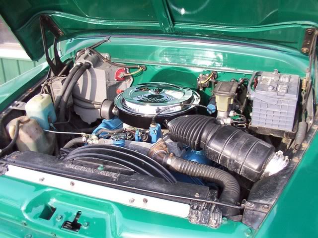
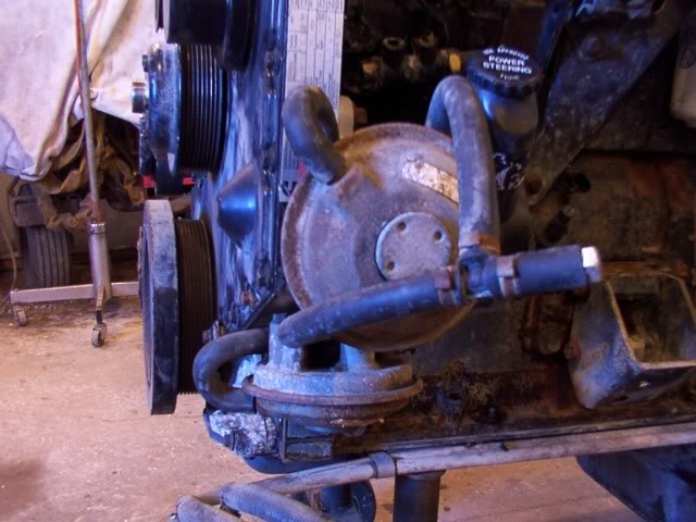
This Cummins engine has a pair of vacuum pumps on it to power the vacuum power brake booster that was on the Dodge truck.
My truck has a hydro power brake booster that is run off the power steering pump so I won't need the vacuum for that.
I'm going to keep the vacuum pump though because I eventually want to put a cruse control unit on the truck and they are powered with a vacuum diafram.
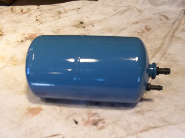
Once I get a cruse control unit, it is going to need a vacuum reserve tank to hold a steady vacuum so I decided to go ahead and make that now.
I'm using an old propane torch tank like this to make the reserve tank out of.
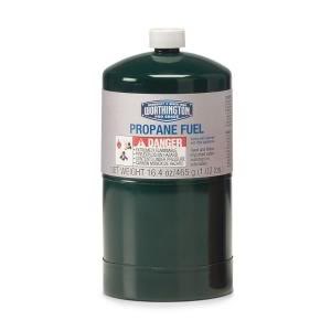
The top of the tank has two valve ports in it.
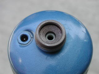
I drilled both of these out and tapped them with a 1/8 NPT thread for hose fittings.
The other end has a thin steel cap on it so it has a flat bottom.
I removed the steel cap so the end is rounded and looks more like a vacuum reserve tank and not a torch tank.
I'll make up the mount for this tank once I figure out where it is going to be mounted.
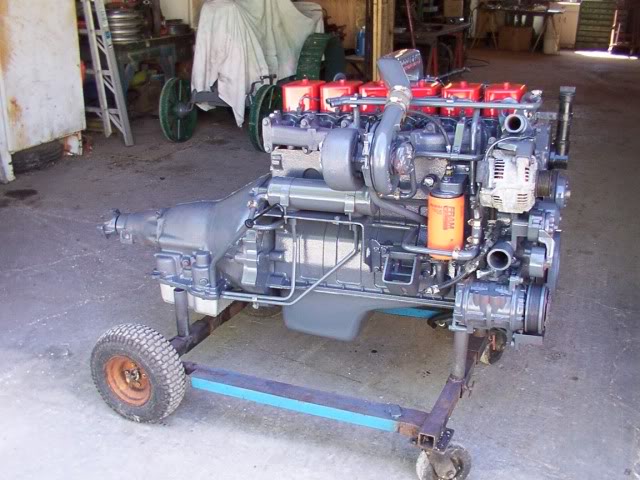
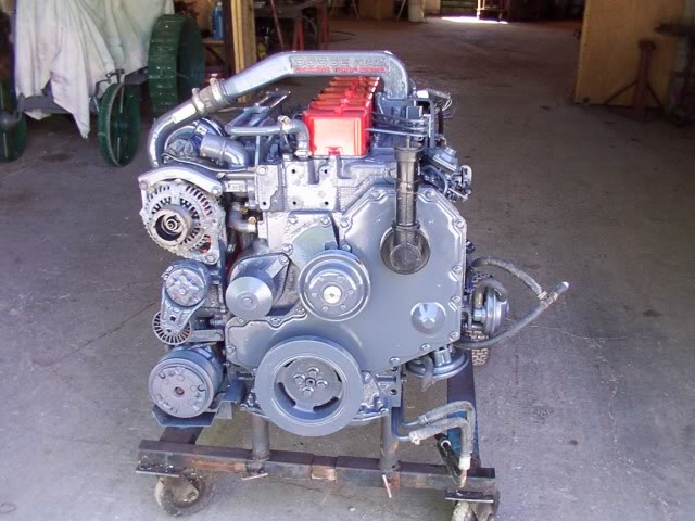
The dowel pin problem has been corrected and the engine is all masked off and primed.
The engine is ready to go in.
All I have to do now is wait for the engine to sell that is currently in the Chevy and then I can take it out and start putting the Cummins in.
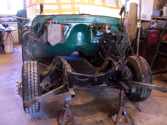
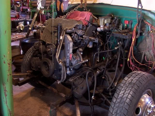
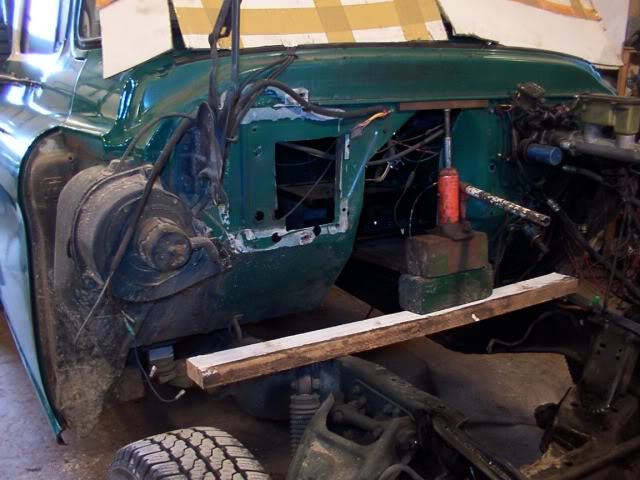
Pulled the truck into the garage to get started on it.
I realize this photo doesn't show that much but this is the end result of about 5 hours of work.
The engine and transmission are all unhooked and ready to bring the forklift in and take this engine out.
The 6.2 engine is comming out out of the truck.
This is the space that I have to work with.
I took the Chevy motor mounts off the frame and they are going with the old engine.

When checking the preliminary dimensions for putting the Cummins in here, it looked like the engine might be just a tad longer than the space in the engine compartment.
It was hard to get an accurate measurement with the 6.2 setting in there but my assumption was correct.
If the Cummings is sitting up against the setback in the firewall, the fan will be sitting about 3/4 inch too far forward.
There is no room to move the radiator any farther forward so I'm going to have to cut the firewall and move it back about 1-1/2 inch.
Originally I wanted to keep my aluminum radiator that I had used for the 6.2 engine.
Turns out that isn't going to work.
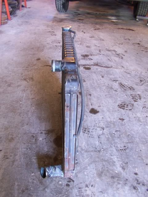
The 6.2 radiator has the inlet and outlet on opposite sides and the Cummins requires the inlet and outlet to be on the same side.
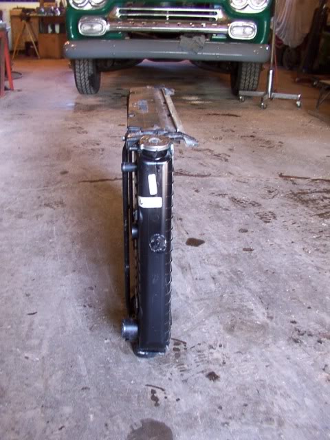
Here are the 6.2 radiator and the Cummins radiator.
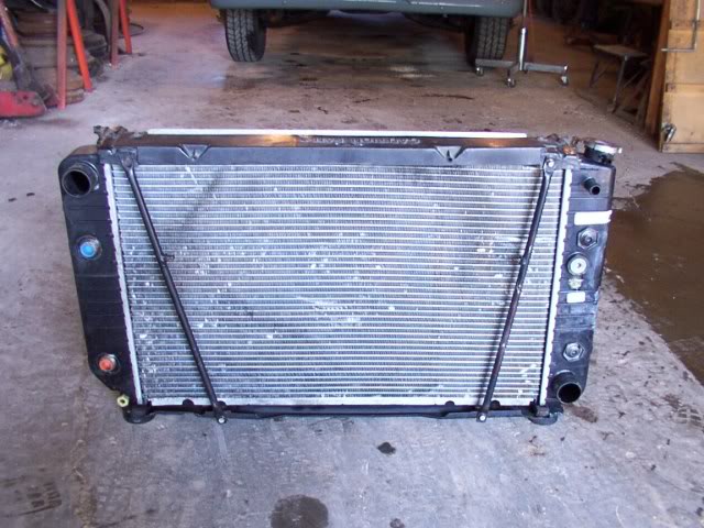
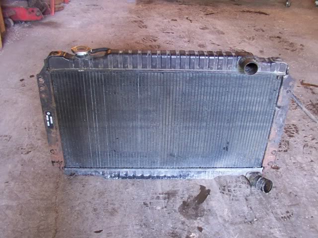
It also turns out that this could be a blessing in disguise.
The Cummins radiator is about 1-1/2 inch thinner than the 6.2 radiator so I just may not have to move the center of the firewall back.
Here are the 6.2 radiator and the Cummins radiator.
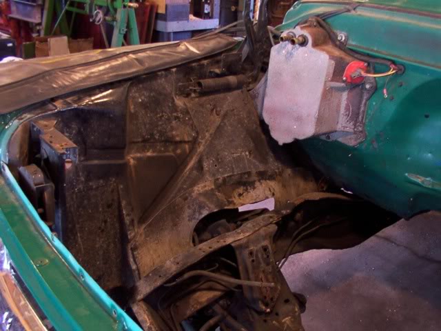
The 6.2 engine had the fuel supply and return lines on the passenger side of the block and the Cummins has the fuel lines on the drivers side of the block so I took the fuel filter off the passenger side fender well.
I also took the radiator overflow tank and the windshield washer tank off the fender well.
These will both be re-located closer to the cab.
My truck has a hydro power brake booster that is run off the power steering pump so I won't need the vacuum for that.
I'm going to keep the vacuum pump though because I eventually want to put a cruse control unit on the truck and they are powered with a vacuum diafram.
Once I get a cruse control unit, it is going to need a vacuum reserve tank to hold a steady vacuum so I decided to go ahead and make that now.
I'm using an old propane torch tank like this to make the reserve tank out of.
The top of the tank has two valve ports in it.
I drilled both of these out and tapped them with a 1/8 NPT thread for hose fittings.
The other end has a thin steel cap on it so it has a flat bottom.
I removed the steel cap so the end is rounded and looks more like a vacuum reserve tank and not a torch tank.
I'll make up the mount for this tank once I figure out where it is going to be mounted.
The dowel pin problem has been corrected and the engine is all masked off and primed.
The engine is ready to go in.
All I have to do now is wait for the engine to sell that is currently in the Chevy and then I can take it out and start putting the Cummins in.
Pulled the truck into the garage to get started on it.
I realize this photo doesn't show that much but this is the end result of about 5 hours of work.
The engine and transmission are all unhooked and ready to bring the forklift in and take this engine out.
The 6.2 engine is comming out out of the truck.
This is the space that I have to work with.
I took the Chevy motor mounts off the frame and they are going with the old engine.
When checking the preliminary dimensions for putting the Cummins in here, it looked like the engine might be just a tad longer than the space in the engine compartment.
It was hard to get an accurate measurement with the 6.2 setting in there but my assumption was correct.
If the Cummings is sitting up against the setback in the firewall, the fan will be sitting about 3/4 inch too far forward.
There is no room to move the radiator any farther forward so I'm going to have to cut the firewall and move it back about 1-1/2 inch.
Originally I wanted to keep my aluminum radiator that I had used for the 6.2 engine.
Turns out that isn't going to work.
The 6.2 radiator has the inlet and outlet on opposite sides and the Cummins requires the inlet and outlet to be on the same side.
Here are the 6.2 radiator and the Cummins radiator.
It also turns out that this could be a blessing in disguise.
The Cummins radiator is about 1-1/2 inch thinner than the 6.2 radiator so I just may not have to move the center of the firewall back.
Here are the 6.2 radiator and the Cummins radiator.
The 6.2 engine had the fuel supply and return lines on the passenger side of the block and the Cummins has the fuel lines on the drivers side of the block so I took the fuel filter off the passenger side fender well.
I also took the radiator overflow tank and the windshield washer tank off the fender well.
These will both be re-located closer to the cab.
Thread Starter
|
Diesel Fan
Joined: Jul 2012
Posts: 11
Likes: 1
I started setting the engine down in the frame to see how everything was going to line up.
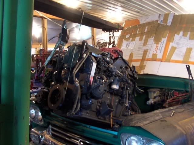
I was hoping that I could cheat on this swap and do it with out removing the front clip.
Well that isn't going to work after all.
This is only a 6-cylinder but it sure is a tall engine.
I got it about 2/3's of the way in and it got stuck with the oil pan on the cross member and the back of the head up against the fire wall.
I need to be able to set it in at a straighter angle and I can't do that with the grille still on.
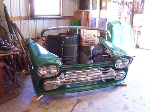
I really was hoping I wouldn't have to remove the front clip.
It's not an easy thing to move around by just one person but here it is off the truck.
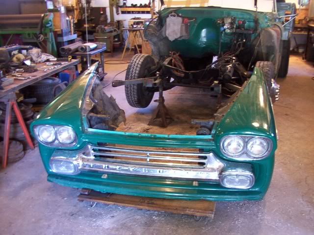
There are parts from the truck setting all around the garage.
My wife has been parking her car out along side the garage for a few days now.
OK .. This should make it a lot easier to fit that engine in.
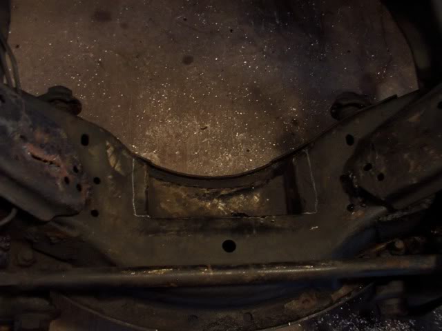
I had already notched the crossmember so the 6.2 oil pan could set down into it to get the transmission and bell housing to slip back under the cab.
However this notch isn't wide enough for the Cummins oil pan.
It only needs to be about 1/4 inch wider but I'm going to open it up to an inch on each side so I have plenty of room for side adjustment on the engine.
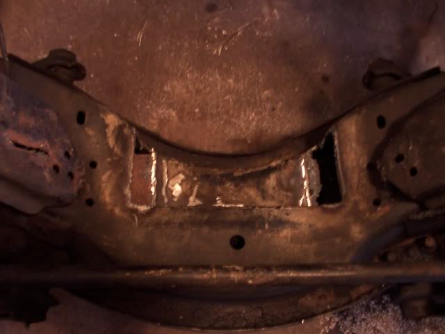
Each side is cut out with the torch.
The modification is completed and primed.
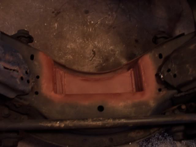
The oil pan can set down into it now and I think it will slip on past once I can level the engine out more.
If not, I'll have to trim some off the back of the notched area.
Right now the air conditioner pump is hanging up on the side of the frame and this is keeping the engine from dropping down in any farther.
Once I notch the frame rail to clear the pump, then the front cross plate is going to keep the engine from setting down where it needs to be.
The front cross plate supports the frame rail so the steering box doesn't twist and the brake lines are mounted to it.
If I remove this cross plate, I can box the front frame rail to support the steering box and then run a piece of angle iron across the underside of the rails to mount the brake lines to.
Slowly making progress. ..
The front cross plate is removed and I trimmed the top of the frame rail on the passenger side to clear the air conditioning pump.
I'm not going to put any supports back in until after the engine is fit into place.
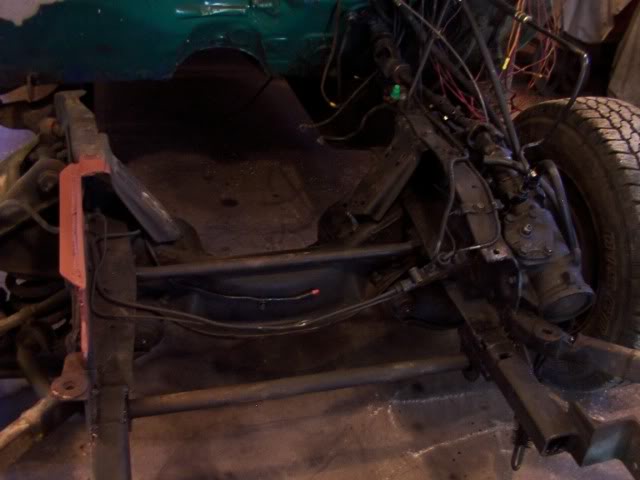
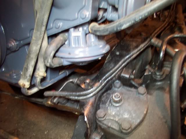
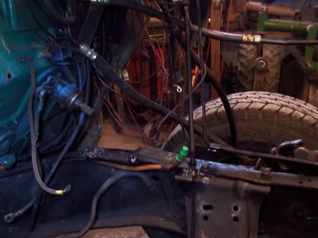
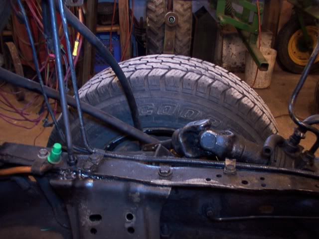
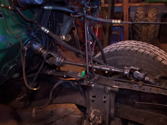
I also moved the fuel lines.
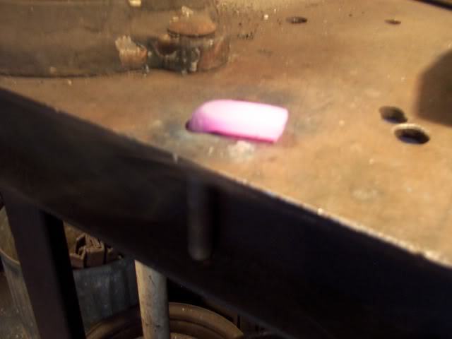
The supply line from the tank that use to run across the front cross plate to the passenger side of the frame now comes up along side the frame under the steering column and has a green plastic cap on it.
The fuel return line that runs along the passenger side of the frame is brought down and fastened to the front of the cross member and has a red cap on it.
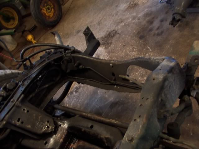
A piece of angle iron is welded to the outside of the frame to add strength for the section of frame that I removed.
The engine is lowered back into the frame and is able to drop down until the Cummins motor mounts hang up on the Chevy frame brackets for the 6.2 motor mounts.
These Chevy frame brackets can't be removed because they are also the support brackets for the upper "A" arms.
I'll remove the Cummins motor mounts for now and make new mounts later.
That lets the engine set down a little farther.
The engine still needs to level out more but the exhaust manifold and the bell housing are both up against the cab.
I was hoping that I could cheat on this swap and do it with out removing the front clip.
Well that isn't going to work after all.
This is only a 6-cylinder but it sure is a tall engine.
I got it about 2/3's of the way in and it got stuck with the oil pan on the cross member and the back of the head up against the fire wall.
I need to be able to set it in at a straighter angle and I can't do that with the grille still on.
I really was hoping I wouldn't have to remove the front clip.
It's not an easy thing to move around by just one person but here it is off the truck.
There are parts from the truck setting all around the garage.
My wife has been parking her car out along side the garage for a few days now.
OK .. This should make it a lot easier to fit that engine in.
I had already notched the crossmember so the 6.2 oil pan could set down into it to get the transmission and bell housing to slip back under the cab.
However this notch isn't wide enough for the Cummins oil pan.
It only needs to be about 1/4 inch wider but I'm going to open it up to an inch on each side so I have plenty of room for side adjustment on the engine.
Each side is cut out with the torch.
The modification is completed and primed.
The oil pan can set down into it now and I think it will slip on past once I can level the engine out more.
If not, I'll have to trim some off the back of the notched area.
Right now the air conditioner pump is hanging up on the side of the frame and this is keeping the engine from dropping down in any farther.
Once I notch the frame rail to clear the pump, then the front cross plate is going to keep the engine from setting down where it needs to be.
The front cross plate supports the frame rail so the steering box doesn't twist and the brake lines are mounted to it.
If I remove this cross plate, I can box the front frame rail to support the steering box and then run a piece of angle iron across the underside of the rails to mount the brake lines to.
Slowly making progress. ..
The front cross plate is removed and I trimmed the top of the frame rail on the passenger side to clear the air conditioning pump.
I'm not going to put any supports back in until after the engine is fit into place.
I also moved the fuel lines.
The supply line from the tank that use to run across the front cross plate to the passenger side of the frame now comes up along side the frame under the steering column and has a green plastic cap on it.
The fuel return line that runs along the passenger side of the frame is brought down and fastened to the front of the cross member and has a red cap on it.
A piece of angle iron is welded to the outside of the frame to add strength for the section of frame that I removed.
The engine is lowered back into the frame and is able to drop down until the Cummins motor mounts hang up on the Chevy frame brackets for the 6.2 motor mounts.
These Chevy frame brackets can't be removed because they are also the support brackets for the upper "A" arms.
I'll remove the Cummins motor mounts for now and make new mounts later.
That lets the engine set down a little farther.
The engine still needs to level out more but the exhaust manifold and the bell housing are both up against the cab.
Thread Starter
|
Diesel Fan
Joined: Jul 2012
Posts: 11
Likes: 1
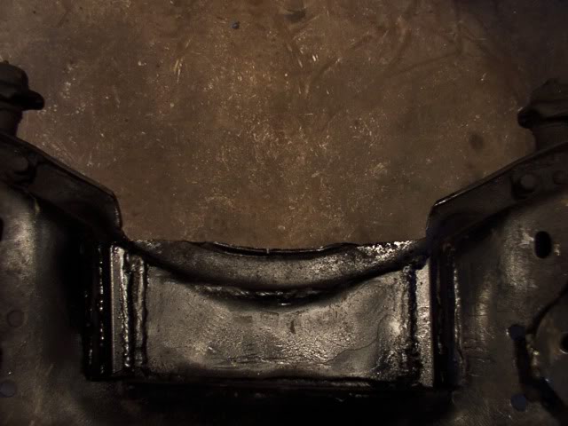
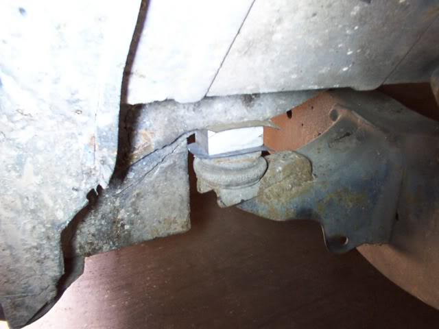
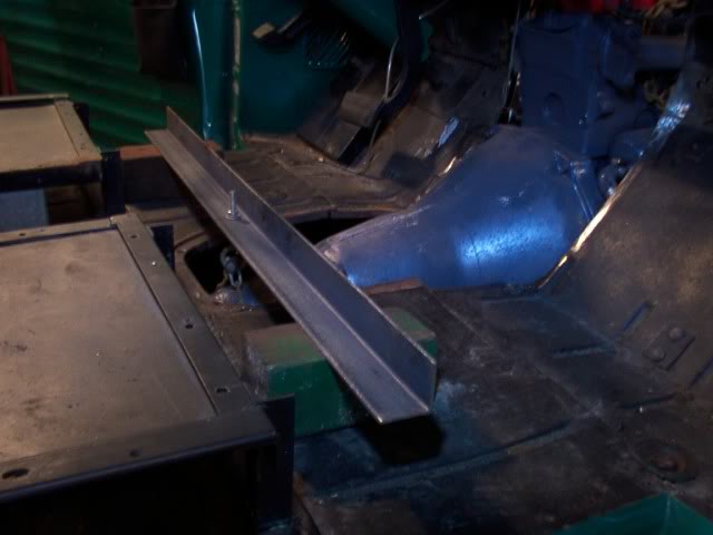
At this point, the oil pan is just catching on the back lip of the frame's cross member so the engine can't level out more.
After lunch, I'll lift the engine back out and trim the lip on the cross member so the oil pan can drop behind it and allow the front of engine to drop down more.
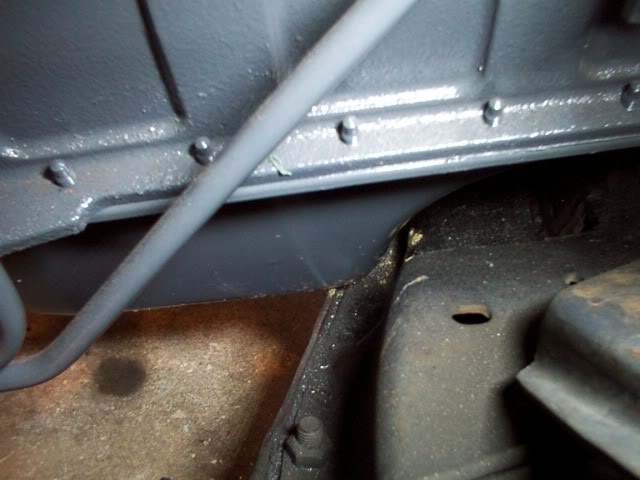
The back edge of the cross member is notched out so the oil pan can clear it.
When I first built this truck back in 95, it didn't have any heater in it.
There was a heater unit out of a 76 Nova up in my storage so I adapted that over to the truck mainly because it was a lot better heater than what these trucks had originally.
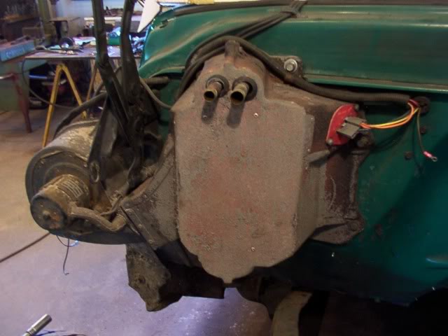
This heater unit is now going to be in the way of the exhaust pipe coming off the turbo.
During this swap, I'm going to update the truck to one of the newer heater / air conditioning units that are available now.
These new units fit completely inside the cab so I figure this is as good a time as any to remove the old heater.
The engine is almost in position now.
It sets low enough but still has to go back about 4 inches.
Part of the fire wall and the bell housing hump are going to have to be modified before the engine will move back any farther.
I did some comparison measurements between the 6.2 engine and the Cummins engines. ...
The 6.2 is 21 inch high from the bottom of the oil pan to the top of the valve covers.
The Cummins is 32 inch high from the bottom of the oil pan to the top of the valve covers ( that's 11 inch higher ).
The 6.2 is 29 inch long from the back of the heads to the front of the fan.
The Cummins is 37 inch long from the back of the head to the front of the fan ( that's 8 inch longer )
I cut the metal out around the bell housing hump.
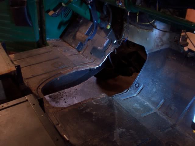
With the engine set back in the frame, I can see that more metal needs to be trimmed around the bell housing.
At this point I can also mark where the firewall needs to be cut out to clear the exhaust.

The indent on the firewall is angled at the top and the valve cover is going to hit this angled area and prevent the engine from going back as far as it needs to go.
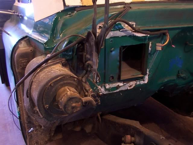
This is how it looks with the metal removed.
The hole at the bottom of the firewall on the drivers side is for the gas
peddle mount.
I'm hoping I can keep the gas peddle mounted at that point.
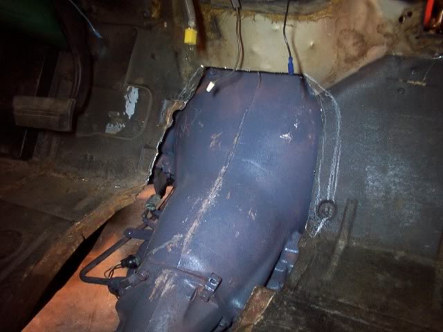
The engine is set back in place and there is good clearance for the exhaust.
If I form metal that goes straight back from the top of the cutout and then down behind the back of the engine, it should allow me room to remove that back valve cover later for adjusting the valves.
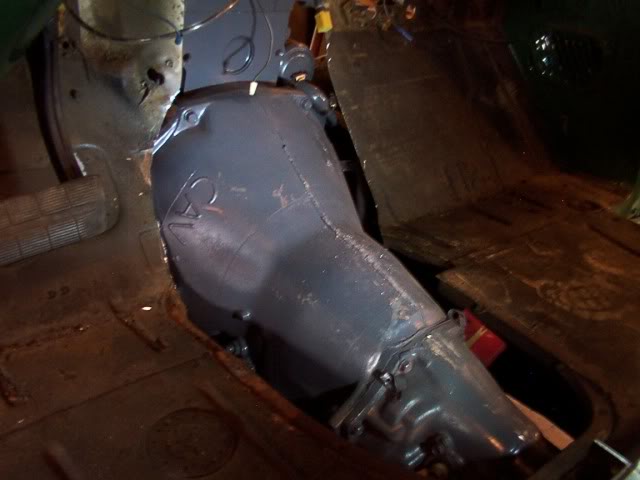
The transmission is fitting good.
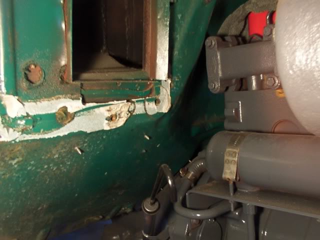
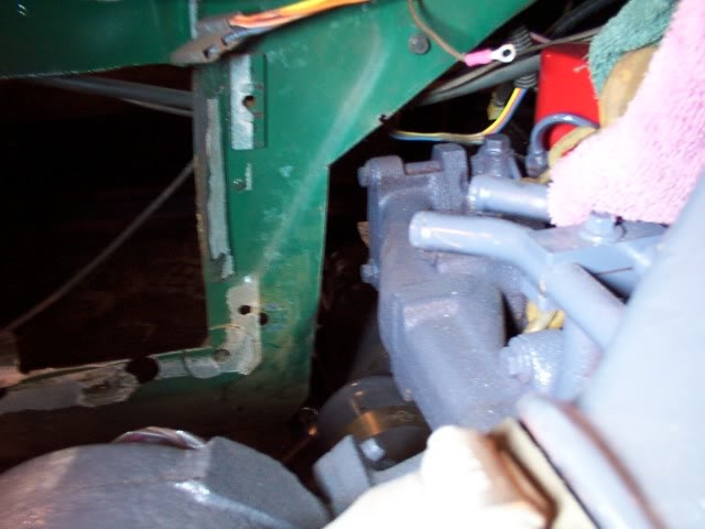
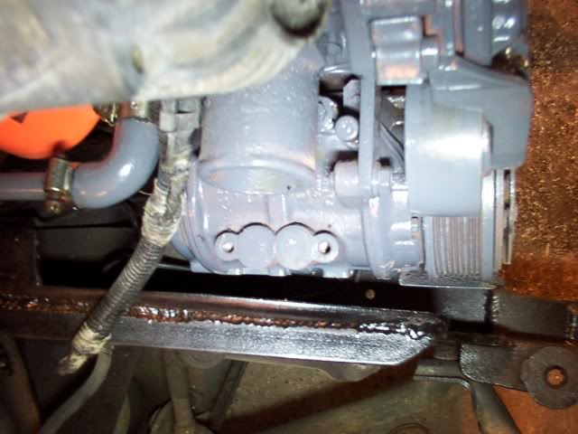
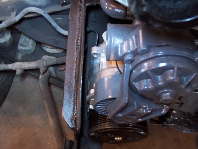
Clearance on the passenger side for the air conditioning pump.
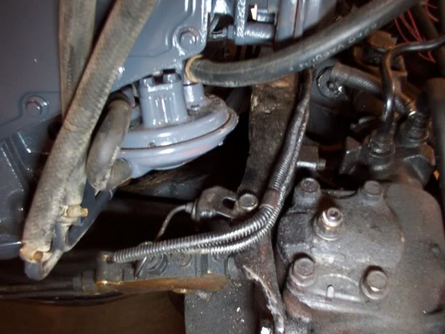
Clearance on the drivers side for the vacuum pumps.
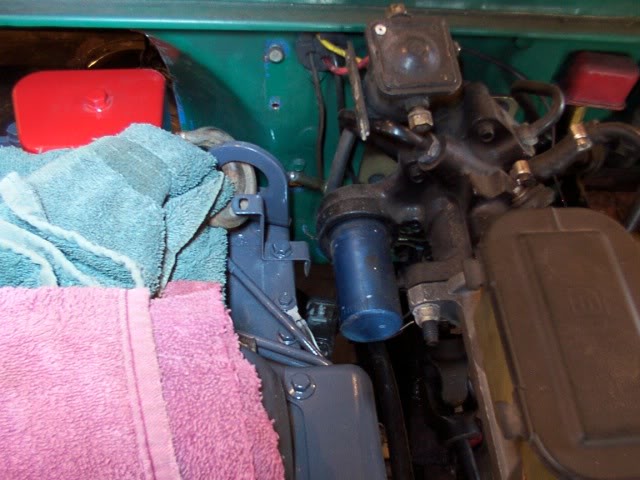
Clearance between the engine and the power brake unit.
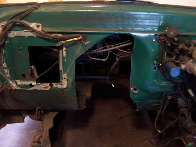
As you can see, it is a tight fit all the way around but it does work.
With that big hole in the firewall, it will make it easier to re-locate the radio right now and I also need to mount the new electric windshield wiper motor up under the cowl.
When those are taken care of, I can then set the engine back in and start on motor mounts.
When the engine is mounted in place, then I'll form new metal for the firewall.
After lunch, I'll lift the engine back out and trim the lip on the cross member so the oil pan can drop behind it and allow the front of engine to drop down more.
The back edge of the cross member is notched out so the oil pan can clear it.
When I first built this truck back in 95, it didn't have any heater in it.
There was a heater unit out of a 76 Nova up in my storage so I adapted that over to the truck mainly because it was a lot better heater than what these trucks had originally.
This heater unit is now going to be in the way of the exhaust pipe coming off the turbo.
During this swap, I'm going to update the truck to one of the newer heater / air conditioning units that are available now.
These new units fit completely inside the cab so I figure this is as good a time as any to remove the old heater.
The engine is almost in position now.
It sets low enough but still has to go back about 4 inches.
Part of the fire wall and the bell housing hump are going to have to be modified before the engine will move back any farther.
I did some comparison measurements between the 6.2 engine and the Cummins engines. ...
The 6.2 is 21 inch high from the bottom of the oil pan to the top of the valve covers.
The Cummins is 32 inch high from the bottom of the oil pan to the top of the valve covers ( that's 11 inch higher ).
The 6.2 is 29 inch long from the back of the heads to the front of the fan.
The Cummins is 37 inch long from the back of the head to the front of the fan ( that's 8 inch longer )
I cut the metal out around the bell housing hump.
With the engine set back in the frame, I can see that more metal needs to be trimmed around the bell housing.
At this point I can also mark where the firewall needs to be cut out to clear the exhaust.
The indent on the firewall is angled at the top and the valve cover is going to hit this angled area and prevent the engine from going back as far as it needs to go.
This is how it looks with the metal removed.
The hole at the bottom of the firewall on the drivers side is for the gas
peddle mount.
I'm hoping I can keep the gas peddle mounted at that point.
The engine is set back in place and there is good clearance for the exhaust.
If I form metal that goes straight back from the top of the cutout and then down behind the back of the engine, it should allow me room to remove that back valve cover later for adjusting the valves.
The transmission is fitting good.
Clearance on the passenger side for the air conditioning pump.
Clearance on the drivers side for the vacuum pumps.
Clearance between the engine and the power brake unit.
As you can see, it is a tight fit all the way around but it does work.
With that big hole in the firewall, it will make it easier to re-locate the radio right now and I also need to mount the new electric windshield wiper motor up under the cowl.
When those are taken care of, I can then set the engine back in and start on motor mounts.
When the engine is mounted in place, then I'll form new metal for the firewall.
Diesel Enthusiast
Joined: Jan 2012
Posts: 469
Likes: 21
From: West Texas
That is a SWEET build!!!! I was thinking of putting a 2nd gen 12 valve into an ol' '55 Chevy second series 2 ton truck, but it fell through and I didnt get to do it. Here is a link to the truck I wanted to do it to:http://s1112.photobucket.com/albums/k485/1955Chevy6400/

I was thinking of putting a 2nd gen 12 valve into an ol' '55 Chevy second series 2 ton truck, but it fell through and I didnt get to do it. Here is a link to the truck I wanted to do it to:http://s1112.photobucket.com/albums/k485/1955Chevy6400/
Thread Starter
|
Diesel Fan
Joined: Jul 2012
Posts: 11
Likes: 1
With the front of the engine setting as low as it can go, there is not enough room under the floor of the csb to raise the transmission enough to level the engine out to where it bneeds to be.
I don't want to cut more of the floor out so I decided to raise the cab some.
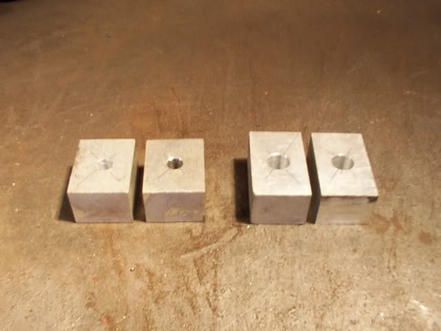
I found two pieces of aluminum that are the same thickness so I cut them each in half and drilled mounting holes in each piece. These will raise the cab 1-1/4 inch.
The back of the cab is going up first so it tilts away from the bed.
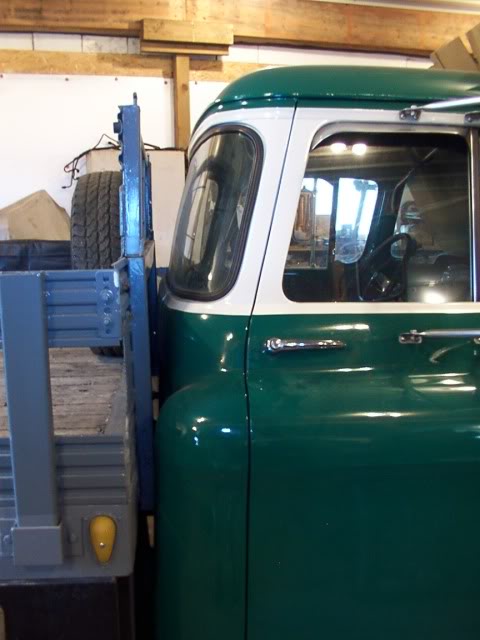
Then the front gets jacked up.
And the riser blocks are set in place.
To prevent oxidation between the aluminum blocks and the steel, I put a piece of rubber on both sides to insulate them from the steel. .
I also coated the bolt shanks with antiseize compound to prevent them from corroding.
 [/QUOTE]
This sets the cab back square with the bed.
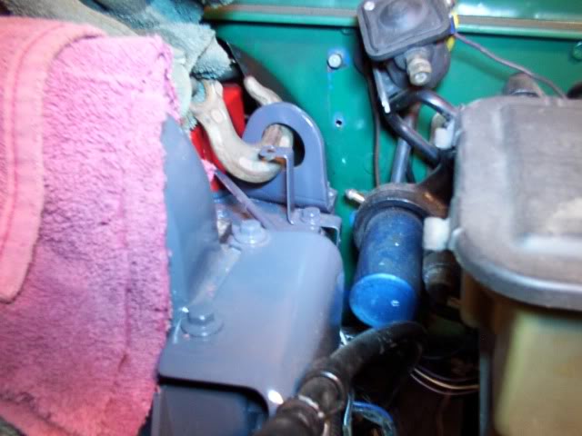
The steering shaft was removed to do this work and you can see here that the brake lines are now setting up off the frame.
Lowering the brake lines back down to the frame is not a problem.
When I built this I formed flex coils in the brake lines coming off the master cylinder so they wouldn't crack from the movement of the cab.
I just stretched these coils out a little to lower the brake lines back down.
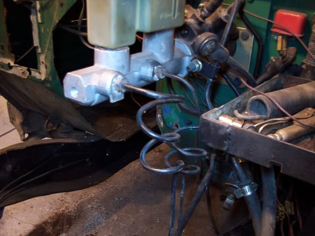
The brake lines are re-mounted on the frame.
then I put the steering shaft back on.
When I pulled the Cummins engine out of the Dodge, the odometer on the Dodge showed 90710 miles.
I want to re-set the odometer on my Chevy to match that so I'll always have the correct mileage for the engine.
First thing is to take the instrument cluster out.
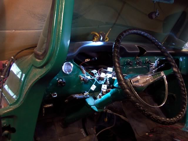
Then I removed the speedometer and took unscrewed the face plate so I could turn it around and get to the odometer.
It currently shows over 26000 on it.

I re-set the odometer to reed 90710 and mounted it back in the cluster.
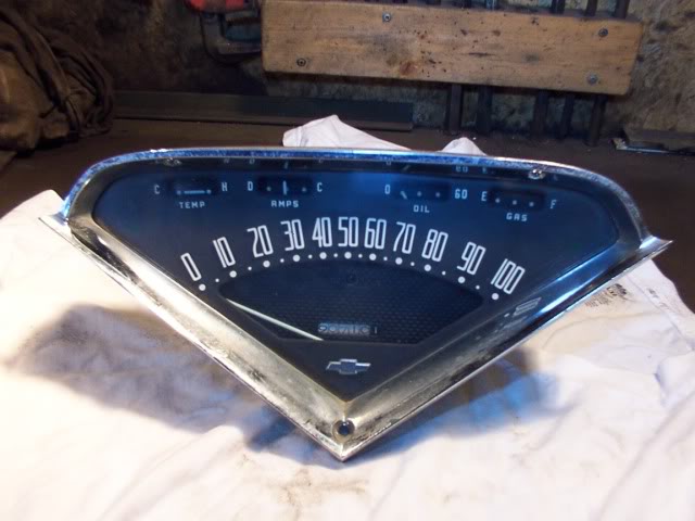
then I put the whole thing back in the dash.
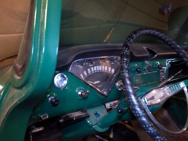
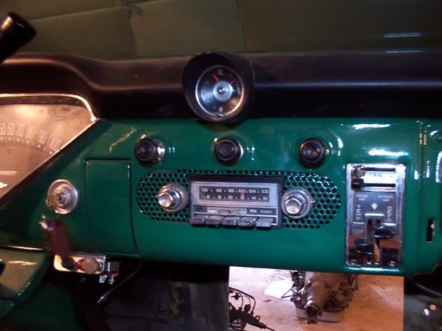
When I got this truck, someone had buggered up the radio hole in the dash so I had cut an oval out and put in a mesh screen and mounted speakers behind it.
Then I used a radio housing from a 57 Desoto and mounted the radio under the dash.
Now the truck is going to have an air conditioner mounted under the dash so I need to move the radio back up into the dash.
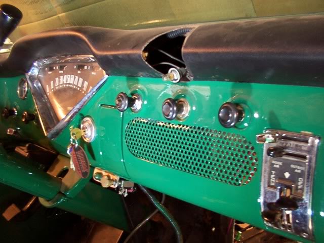
This is the last modification to make before I can set the engine back in and start making motor mounts.
The holes are drilled for the controls and the center is trimmed out for the dial.
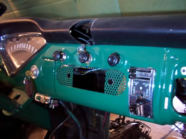
The radio is now mounted back in the dash.
I don't want to cut more of the floor out so I decided to raise the cab some.
I found two pieces of aluminum that are the same thickness so I cut them each in half and drilled mounting holes in each piece. These will raise the cab 1-1/4 inch.
The back of the cab is going up first so it tilts away from the bed.
Then the front gets jacked up.
And the riser blocks are set in place.
To prevent oxidation between the aluminum blocks and the steel, I put a piece of rubber on both sides to insulate them from the steel. .
I also coated the bolt shanks with antiseize compound to prevent them from corroding.
[/QUOTE]This sets the cab back square with the bed.
The steering shaft was removed to do this work and you can see here that the brake lines are now setting up off the frame.
Lowering the brake lines back down to the frame is not a problem.
When I built this I formed flex coils in the brake lines coming off the master cylinder so they wouldn't crack from the movement of the cab.
I just stretched these coils out a little to lower the brake lines back down.
The brake lines are re-mounted on the frame.
then I put the steering shaft back on.
When I pulled the Cummins engine out of the Dodge, the odometer on the Dodge showed 90710 miles.
I want to re-set the odometer on my Chevy to match that so I'll always have the correct mileage for the engine.
First thing is to take the instrument cluster out.
Then I removed the speedometer and took unscrewed the face plate so I could turn it around and get to the odometer.
It currently shows over 26000 on it.
I re-set the odometer to reed 90710 and mounted it back in the cluster.
then I put the whole thing back in the dash.
When I got this truck, someone had buggered up the radio hole in the dash so I had cut an oval out and put in a mesh screen and mounted speakers behind it.
Then I used a radio housing from a 57 Desoto and mounted the radio under the dash.
Now the truck is going to have an air conditioner mounted under the dash so I need to move the radio back up into the dash.
This is the last modification to make before I can set the engine back in and start making motor mounts.
The holes are drilled for the controls and the center is trimmed out for the dial.
The radio is now mounted back in the dash.
Thread Starter
|
Diesel Fan
Joined: Jul 2012
Posts: 11
Likes: 1
I placed a piece of wood on the center of the cross member and set the engine in place so the oil pan is resting on the piece of wood.
It doesn't look like the suspension has squatted any more than it was with the 6.2 engine.
The engine is set back into the firewall where it needs to be.
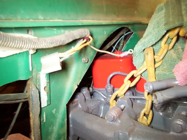
The rear of the transmission has a chain around it and is supported from a hook in this piece of angle iron.
This allows me to be able to fit a transmission support in the frame with out having anything in the way.
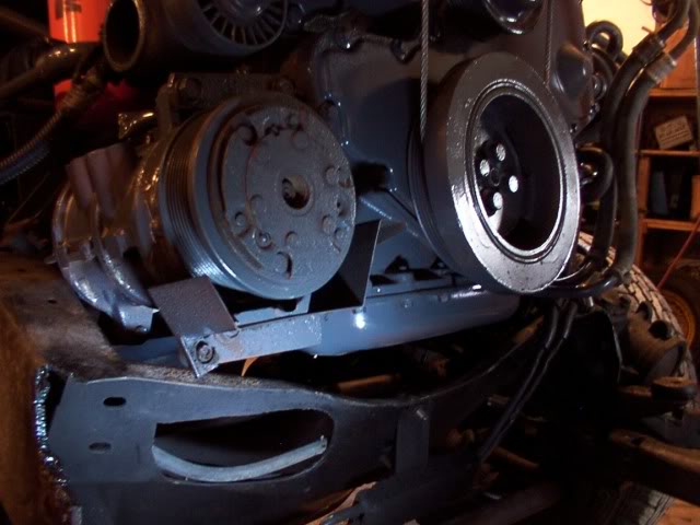
The new air conditioner arrived yesterday so I was able to make the mounts for the pump and bolt it on the engine before I put it in the frame.
The pump mounts are designed so I can unbolt it and pull it forward if I should have to remove it for any reason.
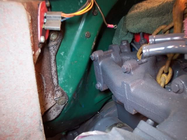
Here is the clearance for the pump.
This is the clearance for the vacuum pump on the other side of the engine.
This is the clearance between the engine and the power brakes.
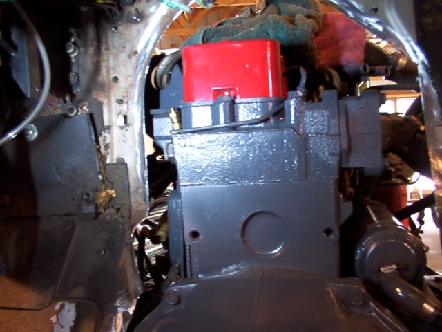
I'm going to end up having to remove more of the firewall for more clearance at the back of the engine.
I decided to just go ahead and take the rest of the indented area out of the firewall.
Because this Chevy frame is narrower than the Dodge frame, I am going with flat motor mounts instead of the angled mounts.
When I put the engine in the frame to gauge the clearance, I set a piece of wood on the cross member and set the oil pan down on it.
Once everything was positioned where it needs to be, I raised the engine and slipped 1/4 inch spacer under the oil pan.
This is to allow for the rubber mounts compressing.
First I cut the mounting lip off the stock Dodge engine mounting bracket.
This piece is bolted to the engine block.
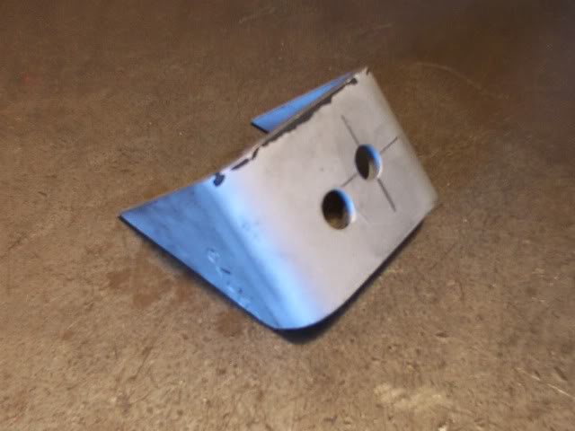
Then I cut a section off a piece of heavy channel.
And trim one side off that piece of channel.
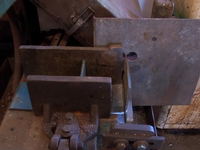
This gives me a "L" bracket that the stock Dodge rubber mount is bolted to.
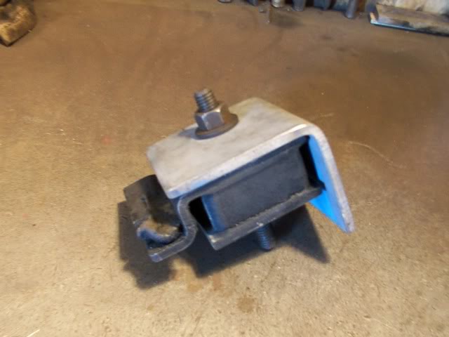
The mounting hole is re-located in the other part of the Dodge engine mounting bracket so it can bolt to the bottom of the rubber mount.
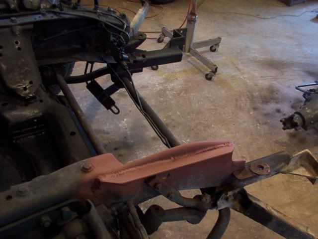
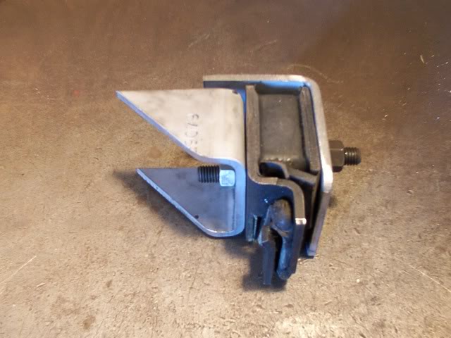
Here's how the motor mount assembly looks so far.
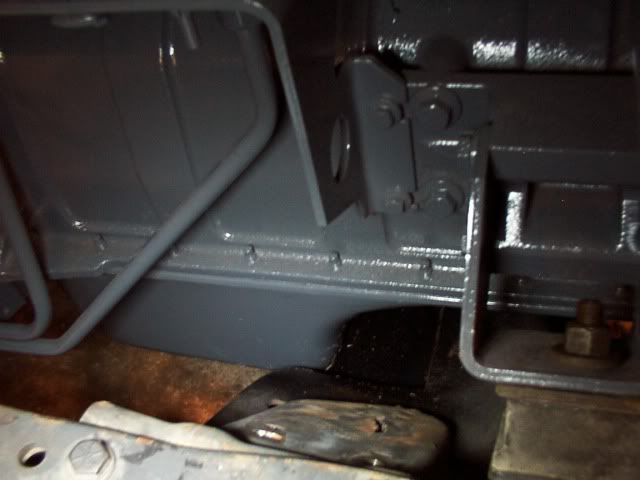
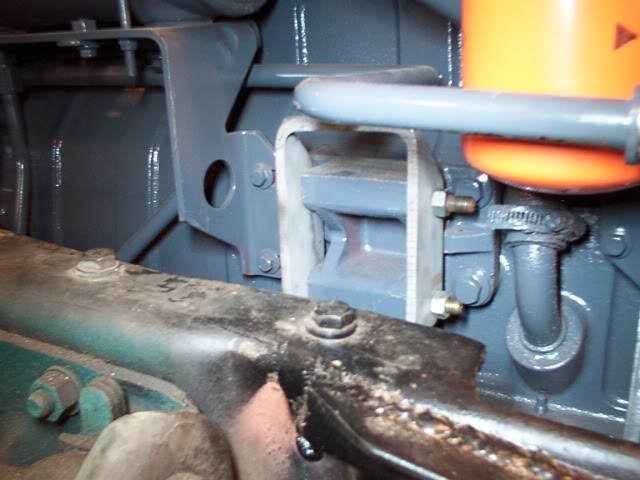
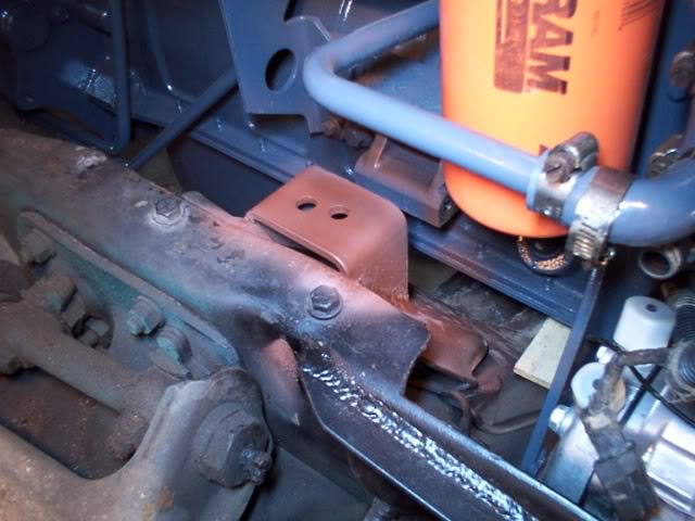
The frame bracket is welded in place and then primed.
The "L" bracket is welded to the engine mounting tabs and triangular shaped pieces of metal are welded to both sides of the "L" bracket for support.
This assembly is then primed and bolted back in place to complete this motor mount.
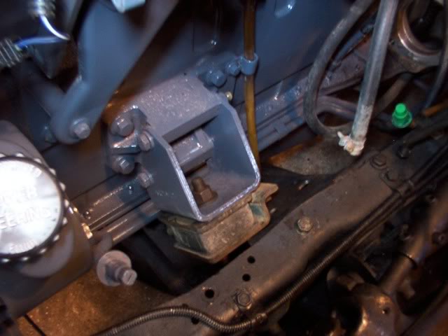
The stack Dodge motor mount has two metal tabs that interlock with each other.
These are safety tabs to keep the engine from lifting if the rubber mount should brake.
In my application, one of these safety tabs could hit the frame as the engine weight pushes down on it so I cut both of these tabs off.
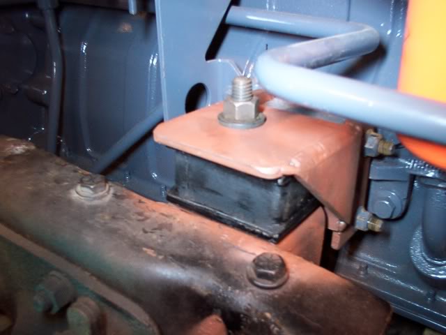
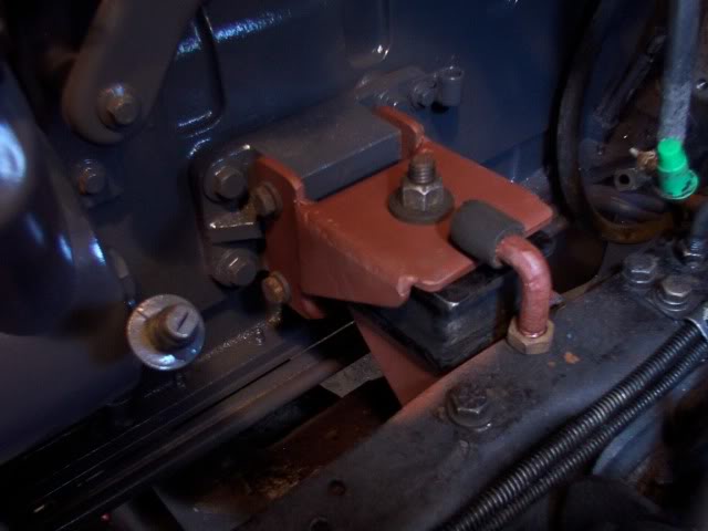
Here is the finished motor mount.
It doesn't look like the suspension has squatted any more than it was with the 6.2 engine.
The engine is set back into the firewall where it needs to be.
The rear of the transmission has a chain around it and is supported from a hook in this piece of angle iron.
This allows me to be able to fit a transmission support in the frame with out having anything in the way.
The new air conditioner arrived yesterday so I was able to make the mounts for the pump and bolt it on the engine before I put it in the frame.
The pump mounts are designed so I can unbolt it and pull it forward if I should have to remove it for any reason.
Here is the clearance for the pump.
This is the clearance for the vacuum pump on the other side of the engine.
This is the clearance between the engine and the power brakes.
I'm going to end up having to remove more of the firewall for more clearance at the back of the engine.
I decided to just go ahead and take the rest of the indented area out of the firewall.
Because this Chevy frame is narrower than the Dodge frame, I am going with flat motor mounts instead of the angled mounts.
When I put the engine in the frame to gauge the clearance, I set a piece of wood on the cross member and set the oil pan down on it.
Once everything was positioned where it needs to be, I raised the engine and slipped 1/4 inch spacer under the oil pan.
This is to allow for the rubber mounts compressing.
First I cut the mounting lip off the stock Dodge engine mounting bracket.
This piece is bolted to the engine block.
Then I cut a section off a piece of heavy channel.
And trim one side off that piece of channel.
This gives me a "L" bracket that the stock Dodge rubber mount is bolted to.
The mounting hole is re-located in the other part of the Dodge engine mounting bracket so it can bolt to the bottom of the rubber mount.
Here's how the motor mount assembly looks so far.
The frame bracket is welded in place and then primed.
The "L" bracket is welded to the engine mounting tabs and triangular shaped pieces of metal are welded to both sides of the "L" bracket for support.
This assembly is then primed and bolted back in place to complete this motor mount.
The stack Dodge motor mount has two metal tabs that interlock with each other.
These are safety tabs to keep the engine from lifting if the rubber mount should brake.
In my application, one of these safety tabs could hit the frame as the engine weight pushes down on it so I cut both of these tabs off.
Here is the finished motor mount.
Thread Starter
|
Diesel Fan
Joined: Jul 2012
Posts: 11
Likes: 1
I drilled and tapped a hole in the frame for a 1/2-20 thread.
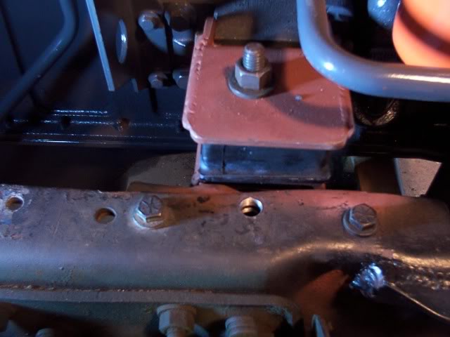
The head is cut off a 1/2-20 bolt and the end was bent over at 90 degrees.
Then I heated the end until it was red hot and flattened it out with a hammer.
A piece of rubber hose was pressed onto the end of the bolt and it was threaded into the hole until the rubber hose just touches the top of the motor mount.
When the rubber mount compresses down it will leave a space between the rubber hose on this safety stop and the top of the motor mount.
If the rubber motor mount should ever brake, this safety stop will not let the engine lift any farther than where it is right now.
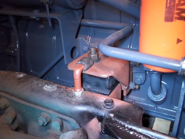
The motor mount on the drivers side is made the same way as the first motor mount.
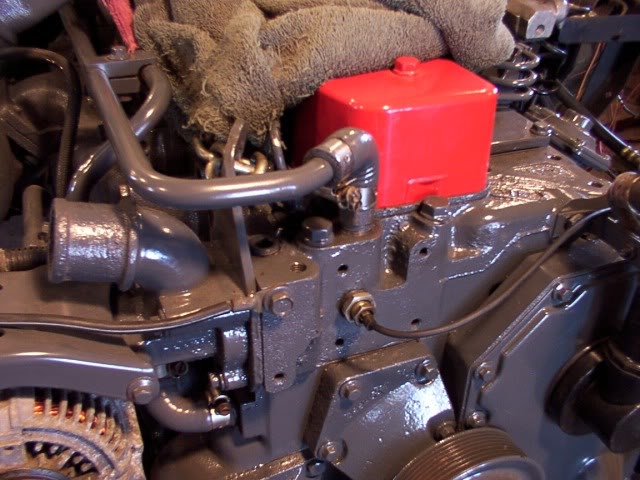
Started working on closing in the firewall and decided that the fitting for the water temperature gauge is still going to be hard to reach so I have decided to move it.
The first thing to do is remove the gauge fitting an plug the hole.
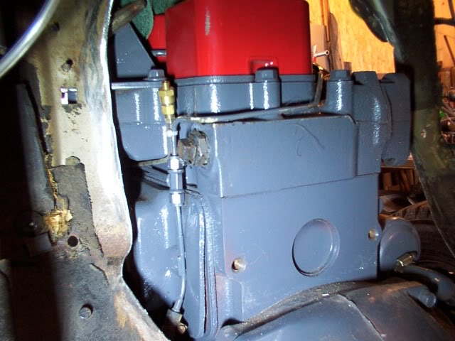
Most engines have other places in the head where you can hook up a temperature gauge or a hose fitting.
This engine does not have any other places to do that.
I removed the heater outlet fitting on the front of the engine and took a look down inside.
There is enough room in the water cavity so I'm going to move the gauge fitting to the front.
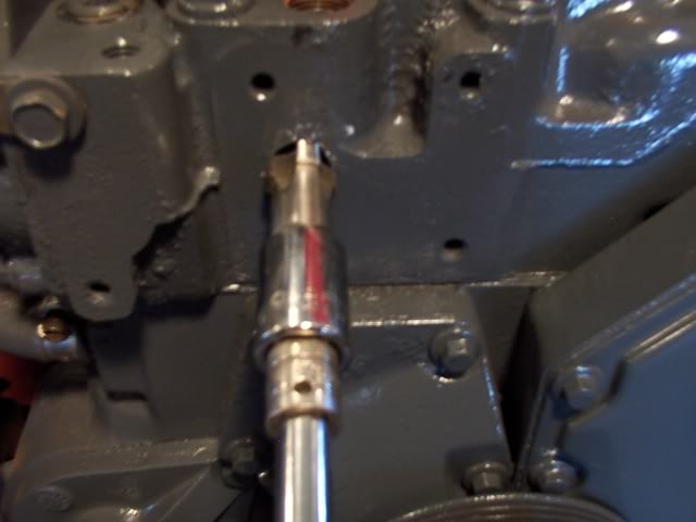
Here I'm starting to drill out the hole.
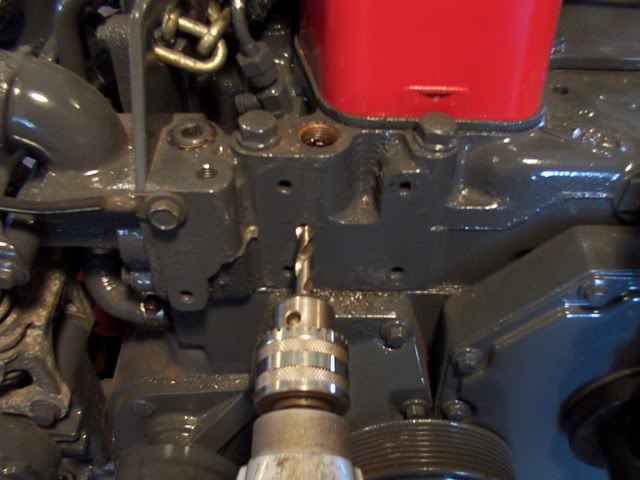
Once the hole is drilled out to the correct size, I thread it with a 1/2 NPT tap.
The gauge fitting is installed and the heater hose line is hooked back up.
Now I can go back to work on the firewall.
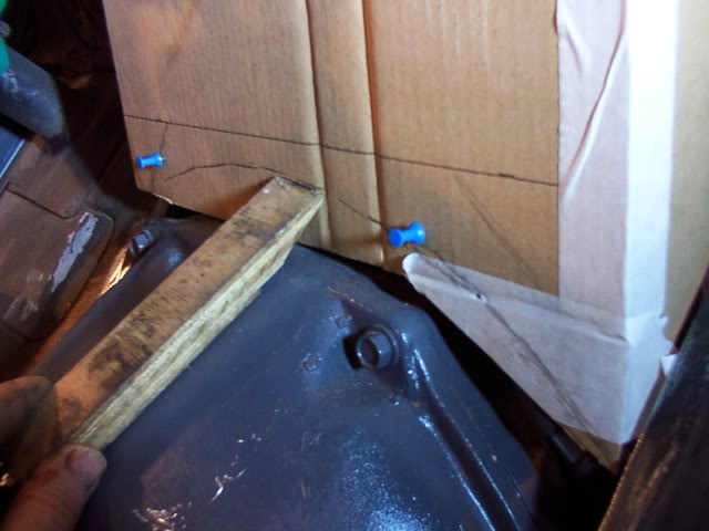
I bolted a 1 inch wood spacer to the back of the block.
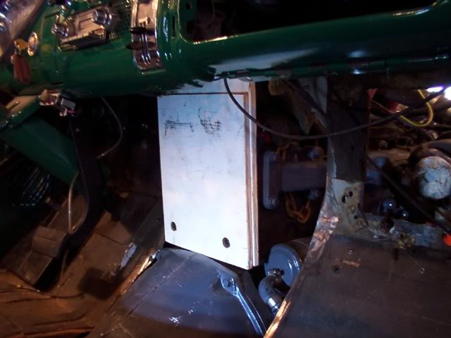
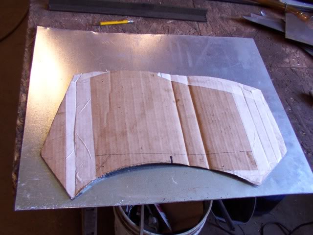
Then I started making the cardboard template for the firewall and fastened it to the wood with thumb tacks.
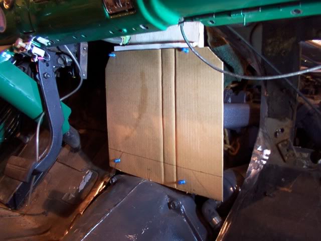
The side sections are fitted and held in place with tape.
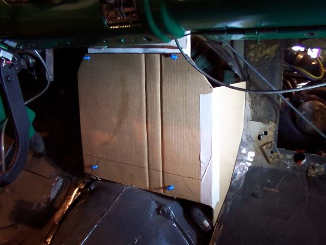
I use a piece of wood to mark where the cut needs to be for clearance above the bell housing.
Once the template is finished, I trace it out on a piece of metal and cut it out.
The metal is then formed and tack welded in place on the firewall.
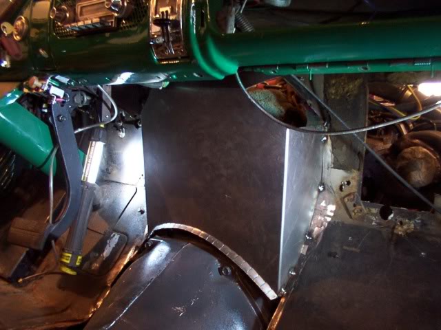
The front of the floor panel had to be trimmed back a little and then I fastened it back in place.
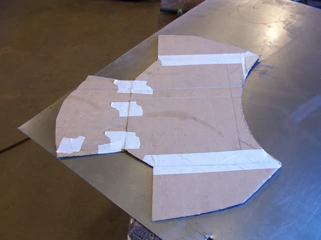
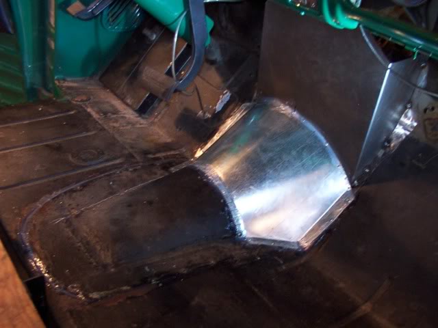
A template is made up for the bell housing cover.
This piece is going to be riveted on instead of welding it so it is cut out of a piece of galvanized steel.
The bell housing cover is fastened in place.
Both the floor panel and this bell housing cover were sealed with a bead of silicone sealant before they were fastened down.
The head is cut off a 1/2-20 bolt and the end was bent over at 90 degrees.
Then I heated the end until it was red hot and flattened it out with a hammer.
A piece of rubber hose was pressed onto the end of the bolt and it was threaded into the hole until the rubber hose just touches the top of the motor mount.
When the rubber mount compresses down it will leave a space between the rubber hose on this safety stop and the top of the motor mount.
If the rubber motor mount should ever brake, this safety stop will not let the engine lift any farther than where it is right now.
The motor mount on the drivers side is made the same way as the first motor mount.
Started working on closing in the firewall and decided that the fitting for the water temperature gauge is still going to be hard to reach so I have decided to move it.
The first thing to do is remove the gauge fitting an plug the hole.
Most engines have other places in the head where you can hook up a temperature gauge or a hose fitting.
This engine does not have any other places to do that.
I removed the heater outlet fitting on the front of the engine and took a look down inside.
There is enough room in the water cavity so I'm going to move the gauge fitting to the front.
Here I'm starting to drill out the hole.
Once the hole is drilled out to the correct size, I thread it with a 1/2 NPT tap.
The gauge fitting is installed and the heater hose line is hooked back up.
Now I can go back to work on the firewall.
I bolted a 1 inch wood spacer to the back of the block.
Then I started making the cardboard template for the firewall and fastened it to the wood with thumb tacks.
The side sections are fitted and held in place with tape.
I use a piece of wood to mark where the cut needs to be for clearance above the bell housing.
Once the template is finished, I trace it out on a piece of metal and cut it out.
The metal is then formed and tack welded in place on the firewall.
The front of the floor panel had to be trimmed back a little and then I fastened it back in place.
A template is made up for the bell housing cover.
This piece is going to be riveted on instead of welding it so it is cut out of a piece of galvanized steel.
The bell housing cover is fastened in place.
Both the floor panel and this bell housing cover were sealed with a bead of silicone sealant before they were fastened down.


