
awarded

Thread Starter
|
Diesel Enthusiast
Joined: May 2008
Posts: 200
Likes: 3
From: san diego california
2002 2500 needs new vp, I think this is a job I can tackle myself. Just a few questions, first is the vp mechanically timed to the engine (like the p-pump) or is it all computer controlled? Second do I need some sort of special puller for the pump gear; if so does someone have a pert number and picture of it? Thanks again guys


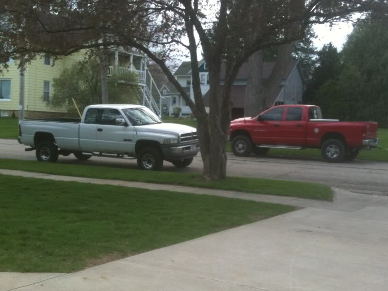
Well as some of you know I FINALLY bought a P-Pump 95 to play with  But she was def. a work truck which doenst scare me. Slowly but surely this truck will get restored and turned into a part time puller and street toy. I'll be taking pictures throughout the process for my own record and so you can guys see what Im up to and maybe help some others or get some input.
  Well heres what I have so far... Enjoy, there will be many more to come.
The lil gem that Ive been searching for...With the NV4500 as well
Fits right in
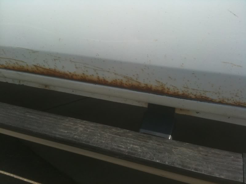
Southern born and raised helped the truck being 99% rust free, another plus
Passenger lip was scabby, drivers was way better...
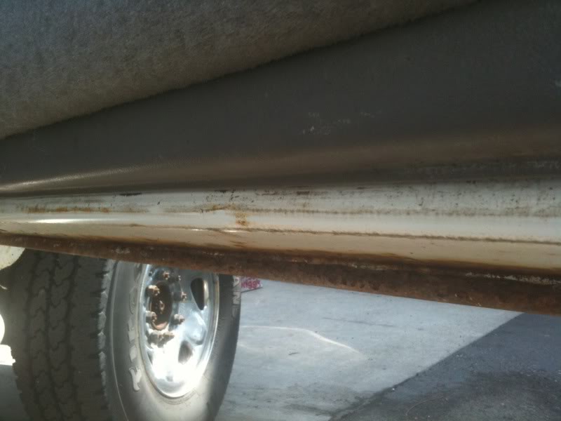
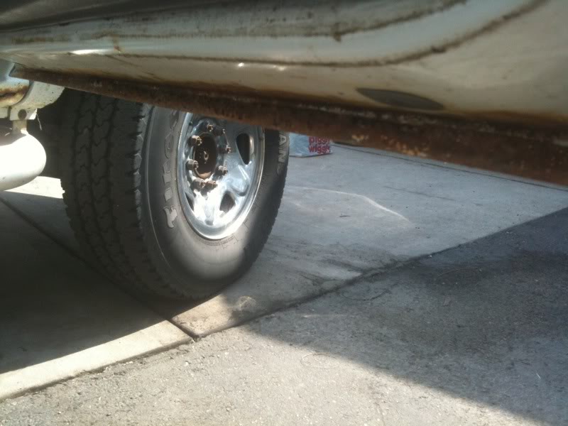
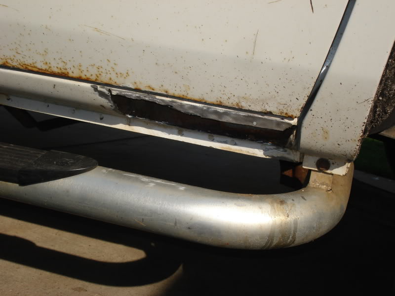
Only rot on the truck
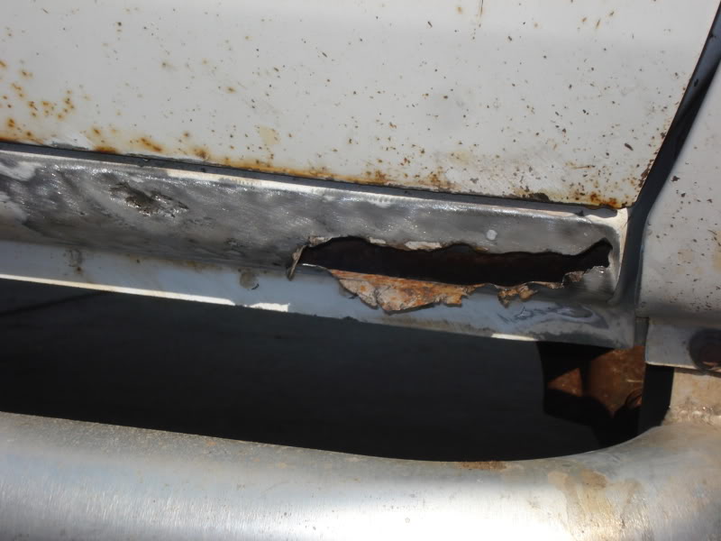
Prepaired for the patch
But she was def. a work truck which doenst scare me. Slowly but surely this truck will get restored and turned into a part time puller and street toy. I'll be taking pictures throughout the process for my own record and so you can guys see what Im up to and maybe help some others or get some input. Well heres what I have so far... Enjoy, there will be many more to come.The lil gem that Ive been searching for...With the NV4500 as well
Fits right in
Southern born and raised helped the truck being 99% rust free, another plus
Passenger lip was scabby, drivers was way better...
Only rot on the truck
Prepaired for the patch
Last edited by Red_Rattler; May 10, 2010 at 05:51 PM.
Diesel Bomber
Joined: Sep 2007
Posts: 7,638
Likes: 638
From: Bend OR
There's a 6 position in-line connector located just behind the dashboard to the right side of your steering column. It carries the wires for cruise control, horn, and the key-in-ignition dinger. You can either clip the black/pink wire coming out of that connector, or for a reversible mod, pull the terminal keeper out of the face of the connector, and unlatch the terminal connected to the black/pink wire. Pull that terminal out of the connector and tape it out of the way so it doesn't ground.
To help in ID'ing the connector here's the wire colors.
Connector 219
Pin 1 - lt blue/black - Cruise control Switch return
Pin 2 - dark blue - Horn
Pin 3 - Lt blue/red - Instrument Panel lamps feed
Pin 4 - Dk green/orange or grey/red or maybe empty
Pin 5 - Black - Ground
Pin 6 - black/pink - Key Warning Switch

Thanks to MIGHTY DIESEL I made my Diesel MIGHTIER!
For Only $130 I once again feel safe running WOT!
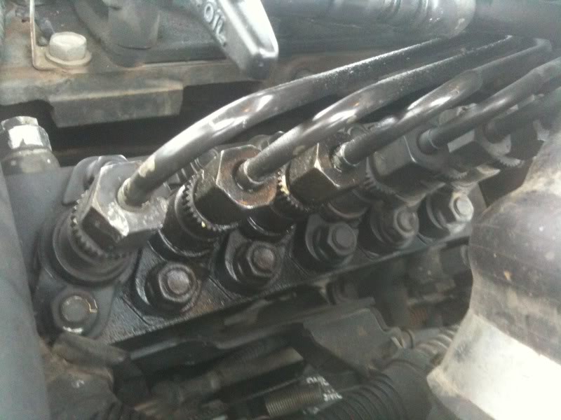
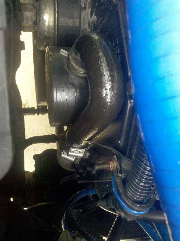
Check the head bolts out here
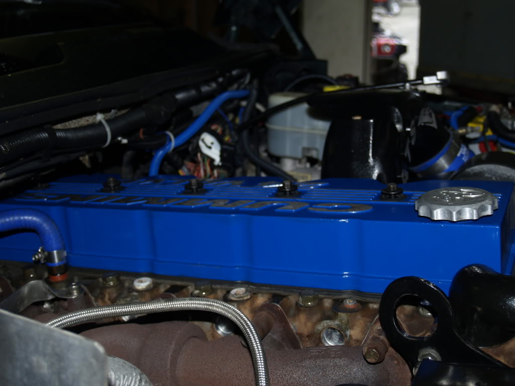
and for the photos... Took 96 Photos Total I went threw and skipped some as i went so here they are
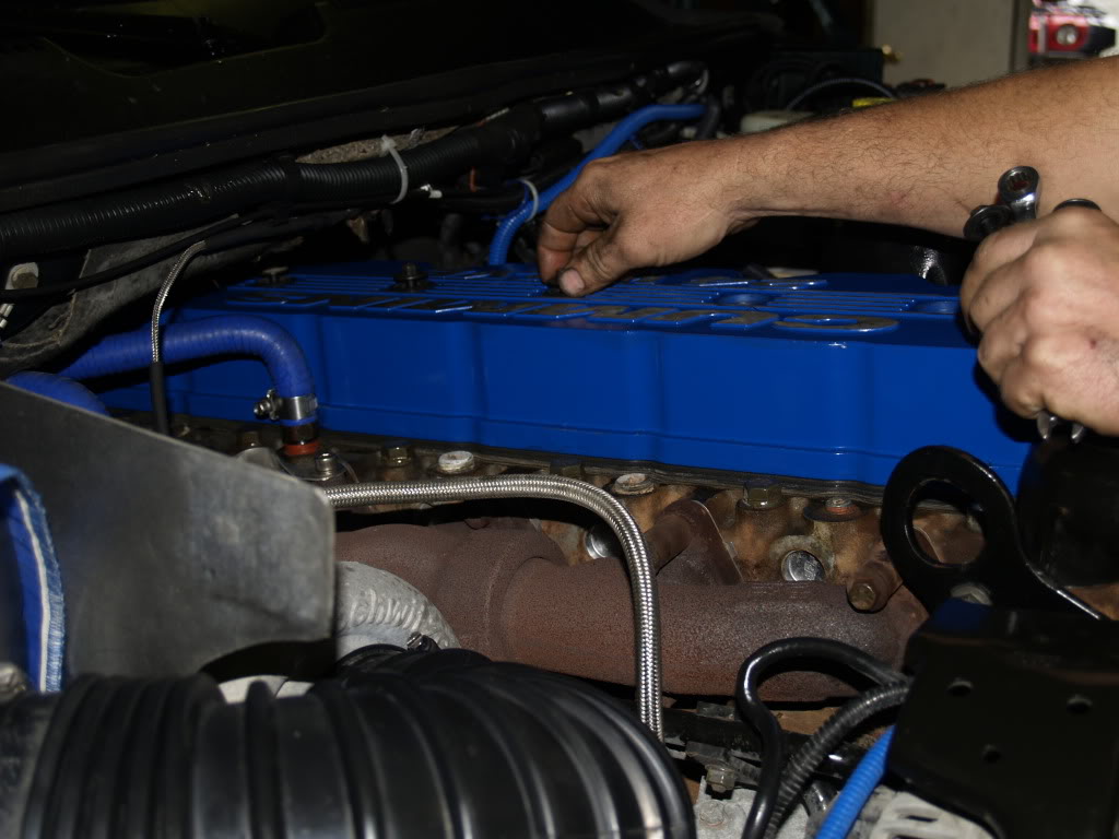
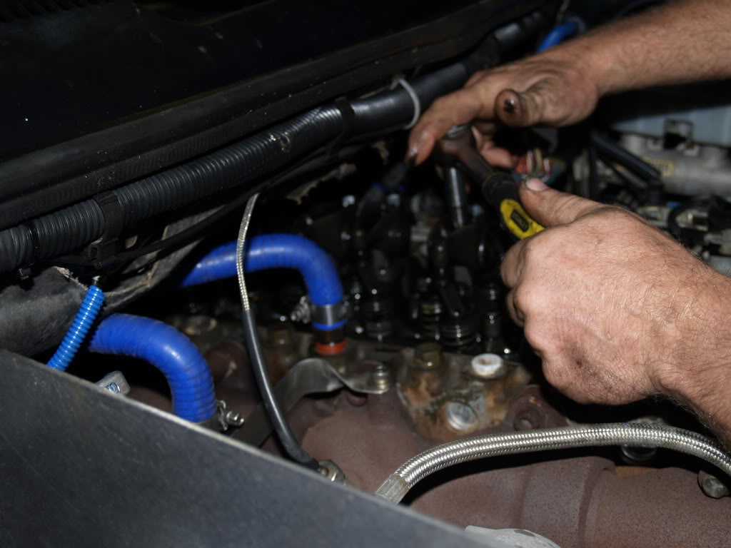
starting to take valve cover off
taking valve cover off
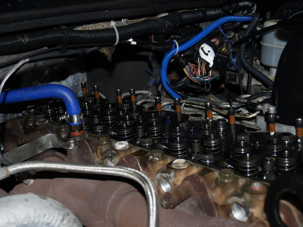
valve cover removed
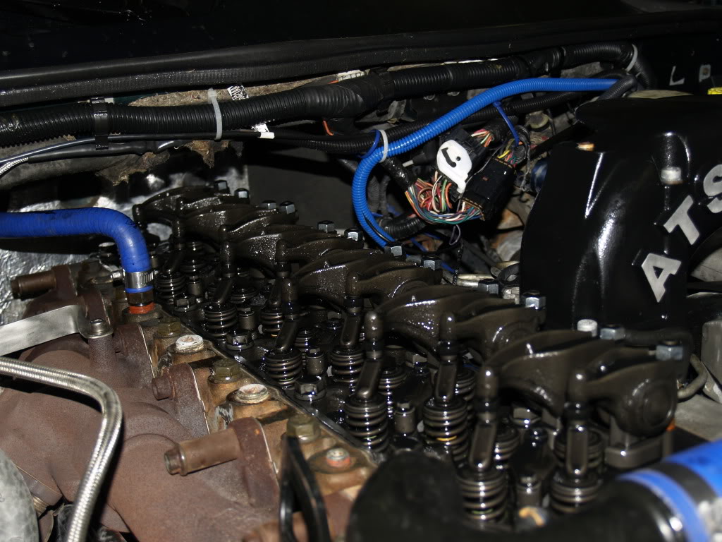
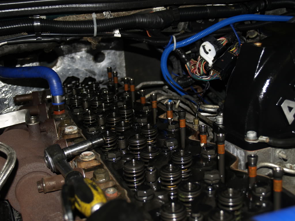
removing rockers
rockers removed
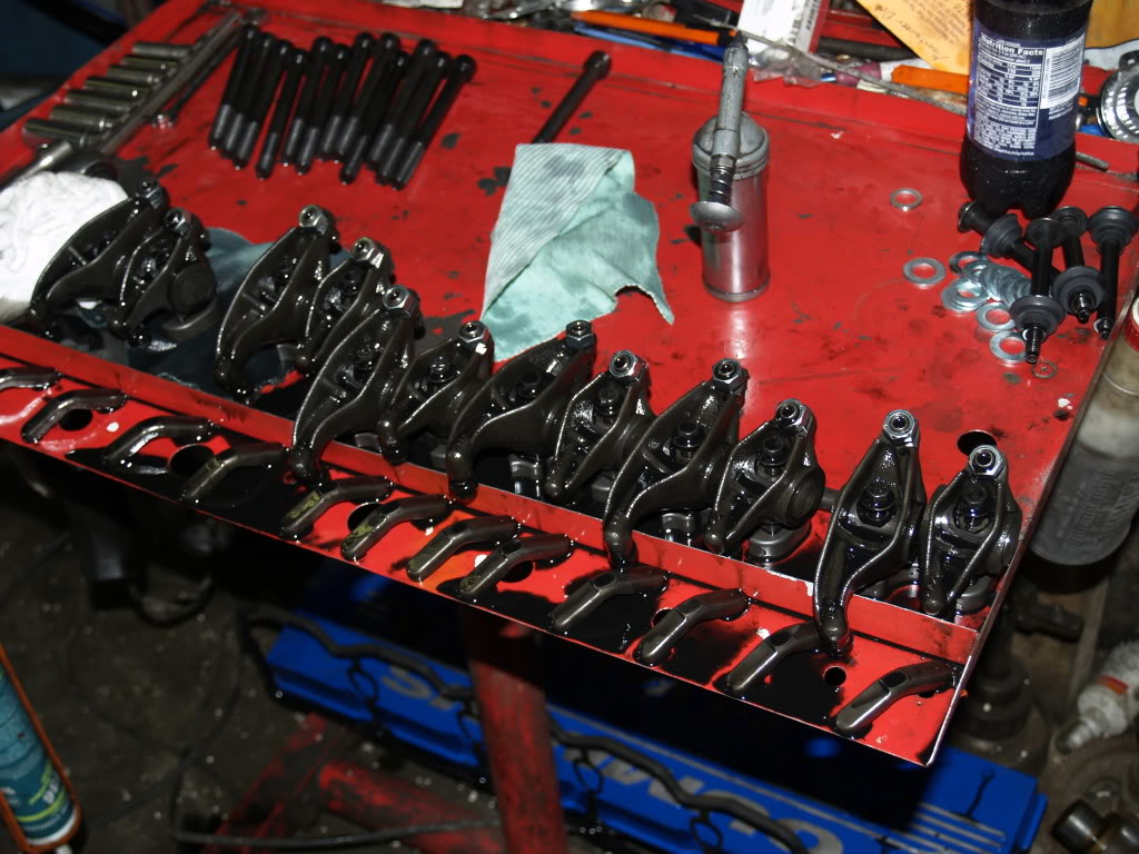
rockers off on table
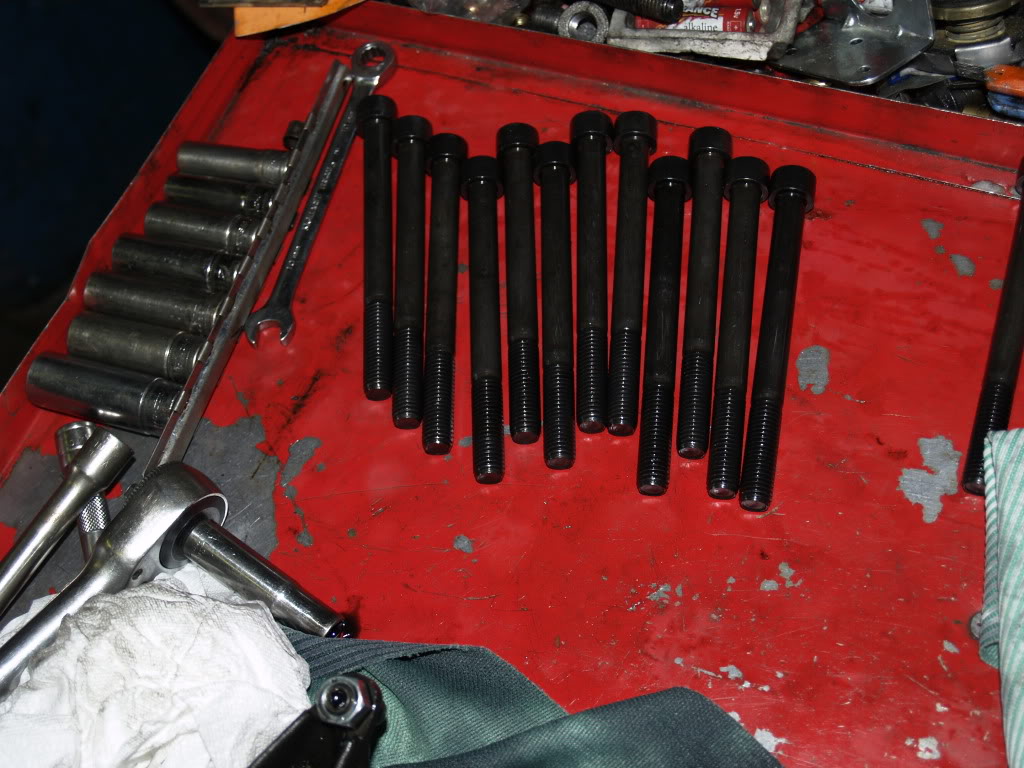
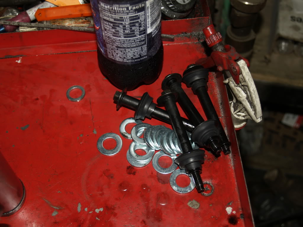
Head bolts on table
head bolt washers and valve cover bolts
installing first bolt
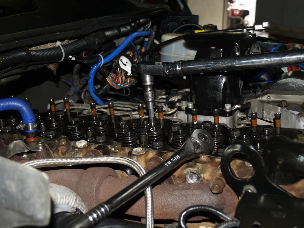
all rockers removed 1 bolt installed
For Only $130 I once again feel safe running WOT!
Check the head bolts out here
and for the photos... Took 96 Photos Total I went threw and skipped some as i went so here they are
starting to take valve cover off
taking valve cover off
valve cover removed
removing rockers
rockers removed
rockers off on table
Head bolts on table
head bolt washers and valve cover bolts
installing first bolt
all rockers removed 1 bolt installed
Last edited by DB Admin; Jun 15, 2010 at 05:50 PM.

Diesel Enthusiast
Joined: Oct 2009
Posts: 375
Likes: 30
From: North Carolina
So, after searching for several hours, on here and on google, and finding nothing, I decided I'd make sure I took pictures and do a quick write up on puling and installing an input shaft. I'd been told by pretty much everyone I talked to that it was really easy, but since I'm not a tranny guy, it kinda made me nervous. First of all, I want to say, yes, it was really easy. There are a few things to remember when pulling it out and reinstalling, but for the most part I think it took me about 15 minutes, and that's because I was taking pictures.
(Note, I don't know all the technical names for all the components, so bear with me!)
So, step one.
Remove the 4 1/2 in bolts holding the input shaft cover on.
Then remove the cover. I used a small flathead screwdriver and a hammer to carefully break the seal, tapping lightly and then prying it away from the front of the transmission.
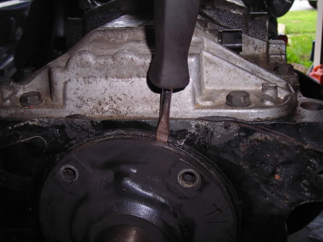
When you take off the cover, take note of the little round divot in the top of the cover, and in the top of the hole on the tranny. Make sure that when reinstalling either the stock cover or the new one, that these holes match up. I haven't received my new input shaft yet, but I plan on running a small bead of silicone around the outside edge of the input shaft cover to help seal it.
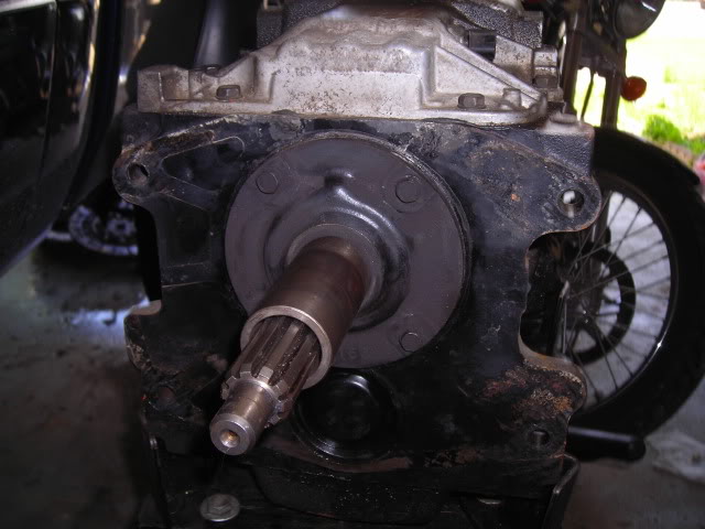
Gently grab the input shaft itself, and carefully pull it out. you may need to wiggle it a little bit, but don't over do it. It should pull out fairly easily.
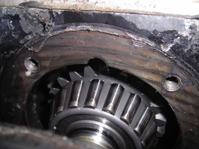
If you look in the center of the input shaft, you'll notice a bearing inside. Make sure this comes out with the input shaft, and doesn't drop down in the tranny...if it does, you'll have to fish it out. Or, it may just sit on the mainshaft inside the tranny. Either way, make sure you have this out.
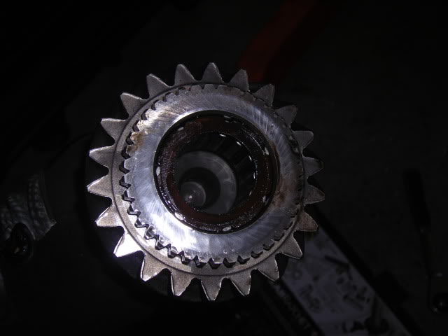
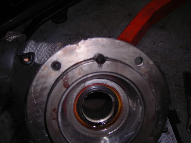
This is what it looks like outside of the input shaft
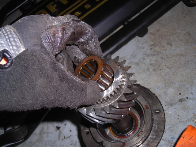
If you look inside the tranny, there's a disc that sit's somewhat loose, with the input shaft removed. I don't know what exactly it is, but I would recommend not moving it around too much....I'm not sure how stable everything behind it is.
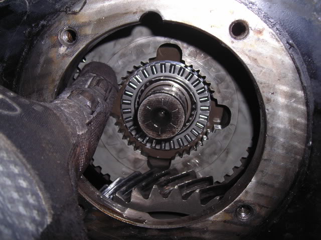
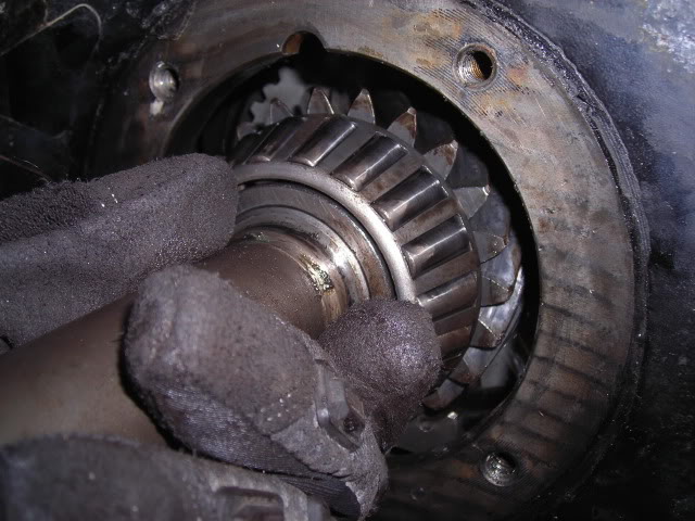
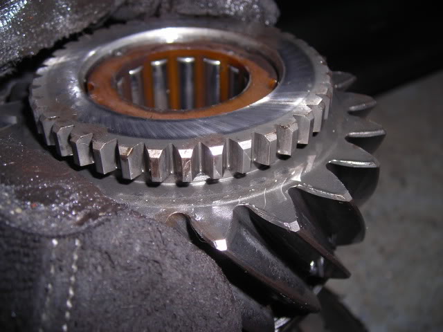
When you're reinstalling the input shaft, take note of the splines on the back of the input shaft. These splines will line up on the inside of that disc that I was talking about. Here's two pics, one of the splines on the input shaft, and one on the disc itself.
I know a lot of people probably already know how to do this, but seeing as how this was the first time for me, I was pretty nervous about pulling it out. I know there have been other people that asked the same question, and everyone pretty much got the same answer....take the bolts off, and pull it out. While it was that easy, it would have been nice to have a few pics to go with it, just to prove that there wasn't anything major to worry about. Hope this helps!
(Note, I don't know all the technical names for all the components, so bear with me!)
So, step one.
Remove the 4 1/2 in bolts holding the input shaft cover on.
Then remove the cover. I used a small flathead screwdriver and a hammer to carefully break the seal, tapping lightly and then prying it away from the front of the transmission.
When you take off the cover, take note of the little round divot in the top of the cover, and in the top of the hole on the tranny. Make sure that when reinstalling either the stock cover or the new one, that these holes match up. I haven't received my new input shaft yet, but I plan on running a small bead of silicone around the outside edge of the input shaft cover to help seal it.
Gently grab the input shaft itself, and carefully pull it out. you may need to wiggle it a little bit, but don't over do it. It should pull out fairly easily.
If you look in the center of the input shaft, you'll notice a bearing inside. Make sure this comes out with the input shaft, and doesn't drop down in the tranny...if it does, you'll have to fish it out. Or, it may just sit on the mainshaft inside the tranny. Either way, make sure you have this out.
This is what it looks like outside of the input shaft
If you look inside the tranny, there's a disc that sit's somewhat loose, with the input shaft removed. I don't know what exactly it is, but I would recommend not moving it around too much....I'm not sure how stable everything behind it is.
When you're reinstalling the input shaft, take note of the splines on the back of the input shaft. These splines will line up on the inside of that disc that I was talking about. Here's two pics, one of the splines on the input shaft, and one on the disc itself.
I know a lot of people probably already know how to do this, but seeing as how this was the first time for me, I was pretty nervous about pulling it out. I know there have been other people that asked the same question, and everyone pretty much got the same answer....take the bolts off, and pull it out. While it was that easy, it would have been nice to have a few pics to go with it, just to prove that there wasn't anything major to worry about. Hope this helps!
Got off the dyno at EEP and click click click , Drew got me all fixed up , THANKS DREW !
Its a common issue on dodge cummins trucks for the starter contacts to fail , with this video you will see how easy it is to replace the contacts yourself and save! Special Thanks to Drew @ http://www.djprecisionmachine.com
Its a common issue on dodge cummins trucks for the starter contacts to fail , with this video you will see how easy it is to replace the contacts yourself and save! Special Thanks to Drew @ http://www.djprecisionmachine.com

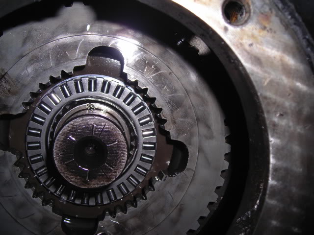
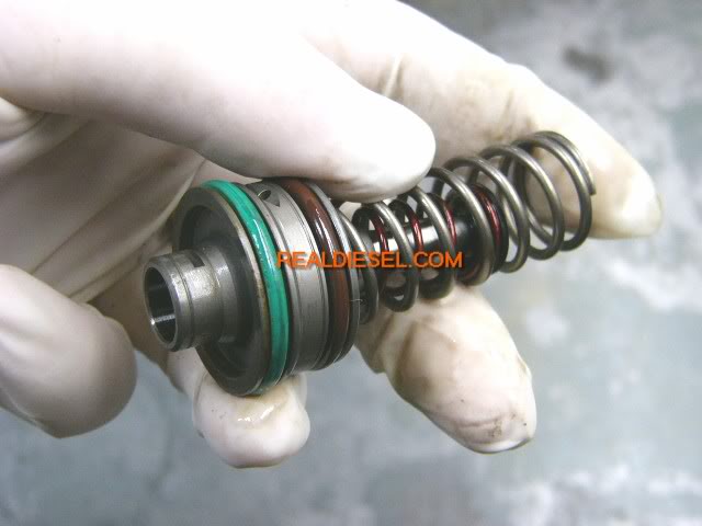
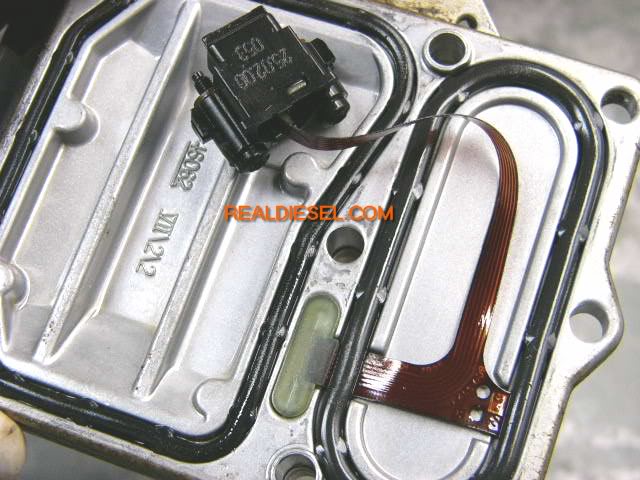
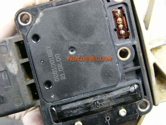
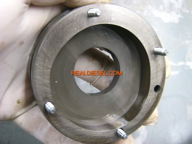
It appears as tho real diesel has closed there doors , we went in to the web archive and rescued these informative photos of the internals of the VP44 Injection pump , thanks to Real Diesel for there work, efforts and support in the Diesel Community
here is a clear view of whats inside the vp44 fuel pump
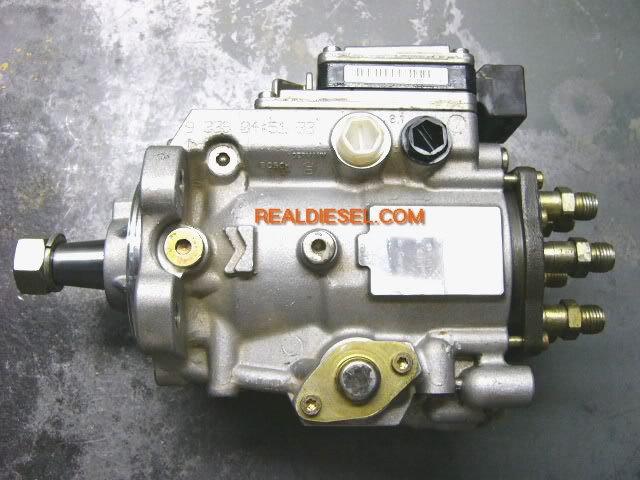
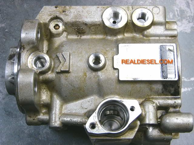

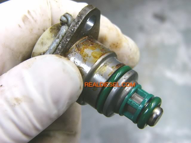
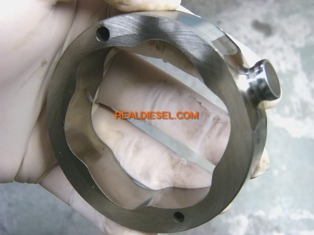
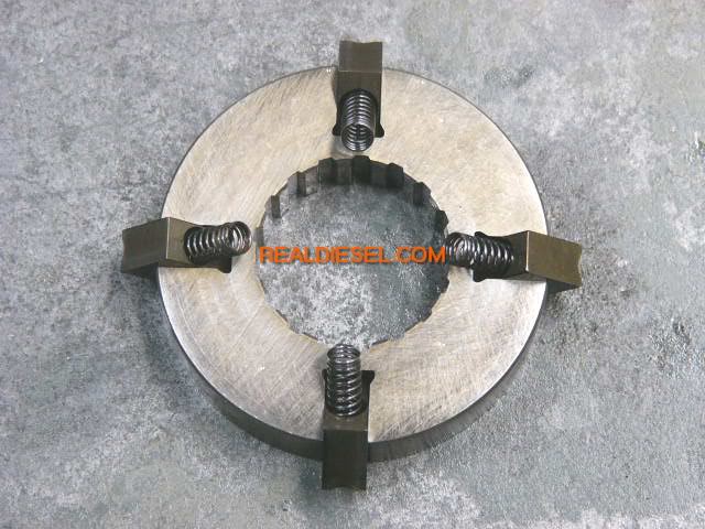
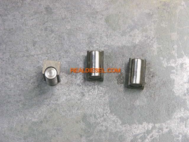
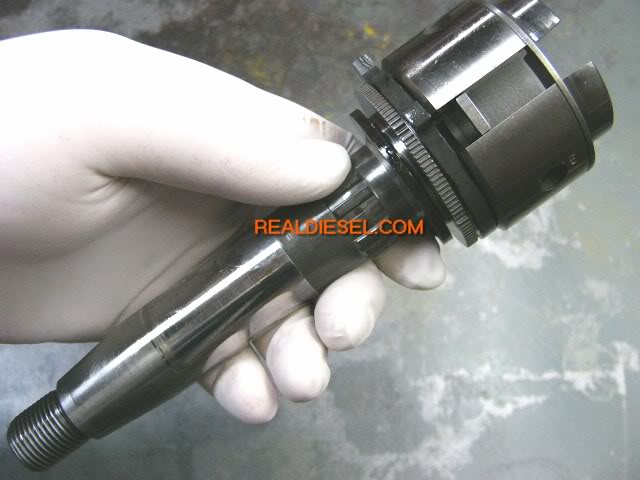
here is a clear view of whats inside the vp44 fuel pump
Last edited by DB Admin; Jul 3, 2010 at 04:04 PM.


