VE pump does not like -76 degree temps


#12
 06-12-2008, 10:19 PM
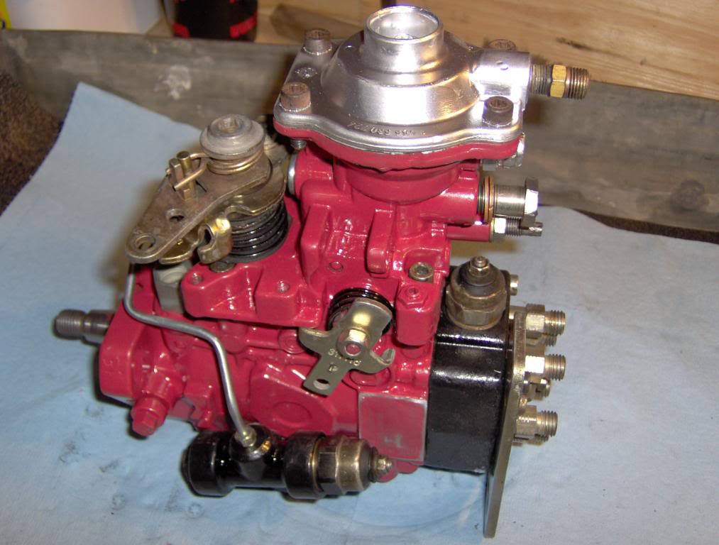
Now lets do the KSB
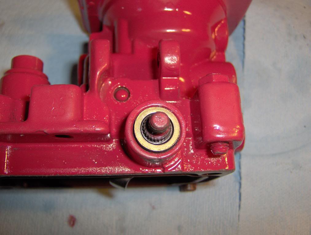
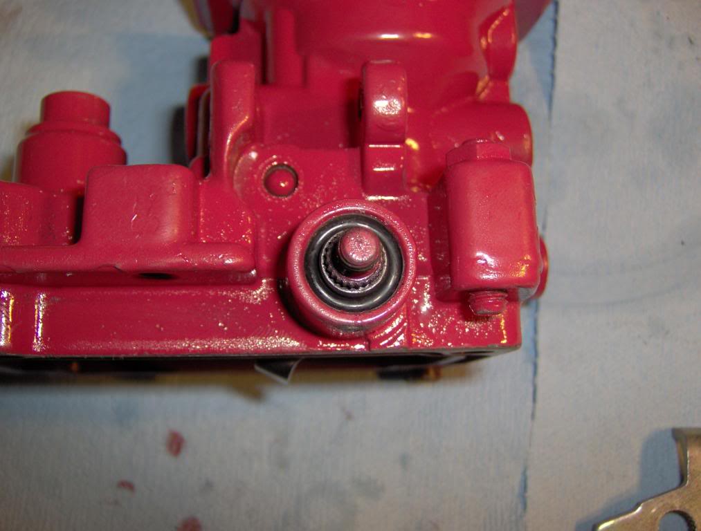
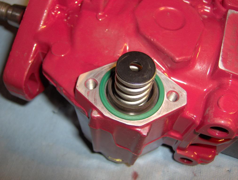
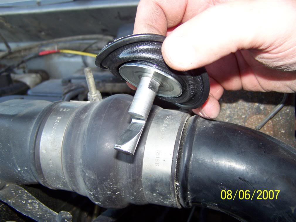
1st remove the Pressure Regulator The bolt on top of the pump there are 3 o-rings on it that need to be replaced.
Then remove the KSB and line and you will find a spring and 2 washers and the o-ring .
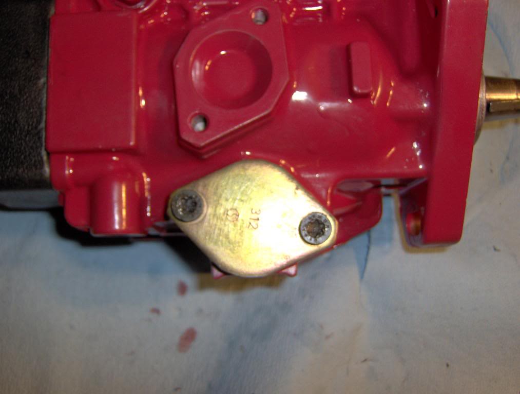
there is another one on the other side of the pump under a cover plate
Here comes the fun part.
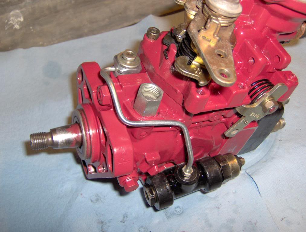
Start by removing the support bracket from the back or the pump head
then place pump on its end if you can but you don't have to. remove the other bolts that hold the head on.
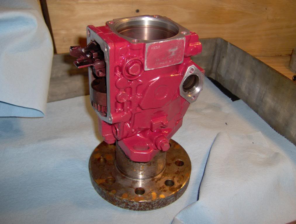
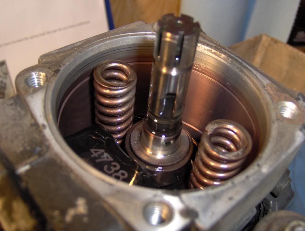
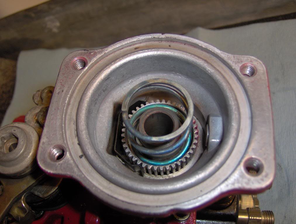
slowly remove the pump head. If you only need to replace this seal you can just loosen the bolts and lift the head high enough to see the o-ring and then remove it and replace it and re install with no probs.
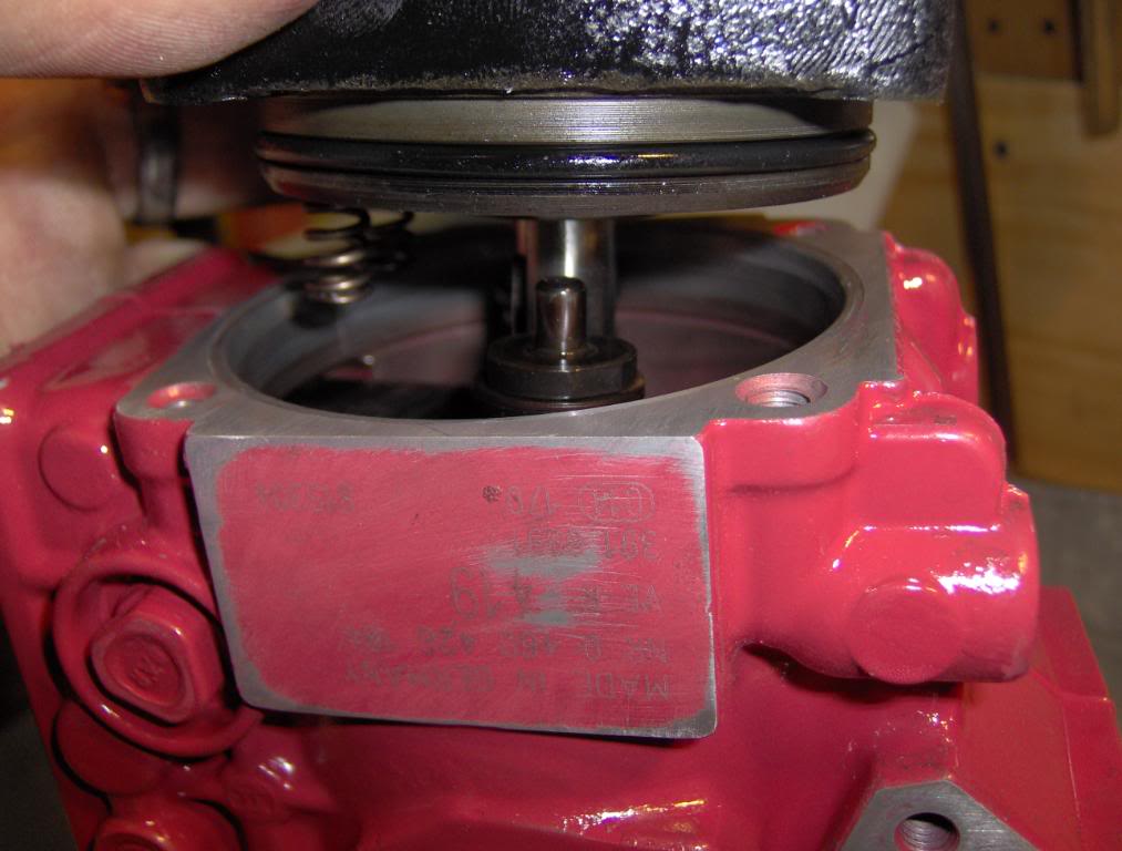
Here are the return springs for the cam plate and plunger.
1st remove the Pressure Regulator The bolt on top of the pump there are 3 o-rings on it that need to be replaced.
Then remove the KSB and line and you will find a spring and 2 washers and the o-ring .
there is another one on the other side of the pump under a cover plate
Here comes the fun part.
Start by removing the support bracket from the back or the pump head
then place pump on its end if you can but you don't have to. remove the other bolts that hold the head on.
slowly remove the pump head. If you only need to replace this seal you can just loosen the bolts and lift the head high enough to see the o-ring and then remove it and replace it and re install with no probs.
Here are the return springs for the cam plate and plunger.
#13
06-12-2008, 10:19 PM
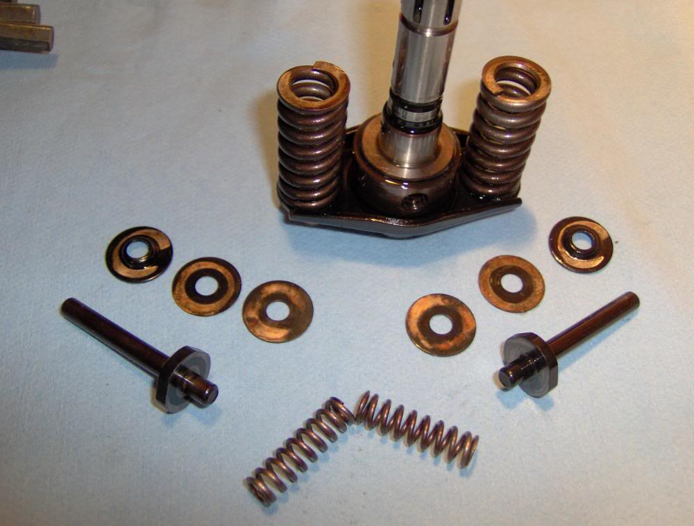
there are also 2 smaller springs that go in the head
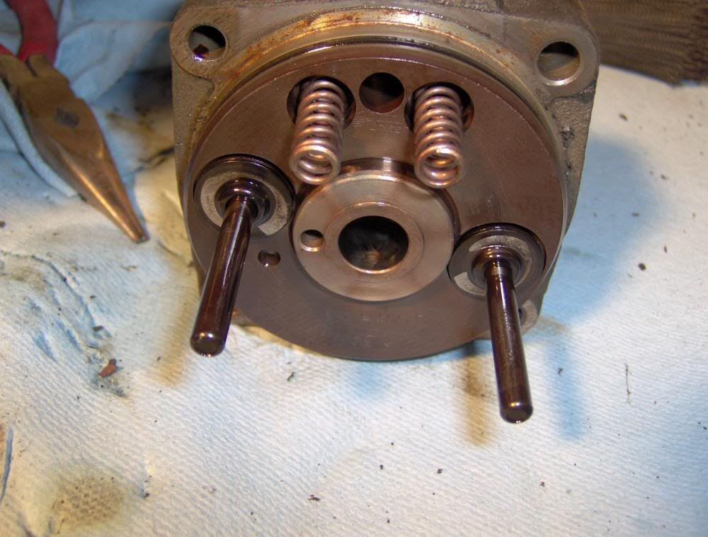
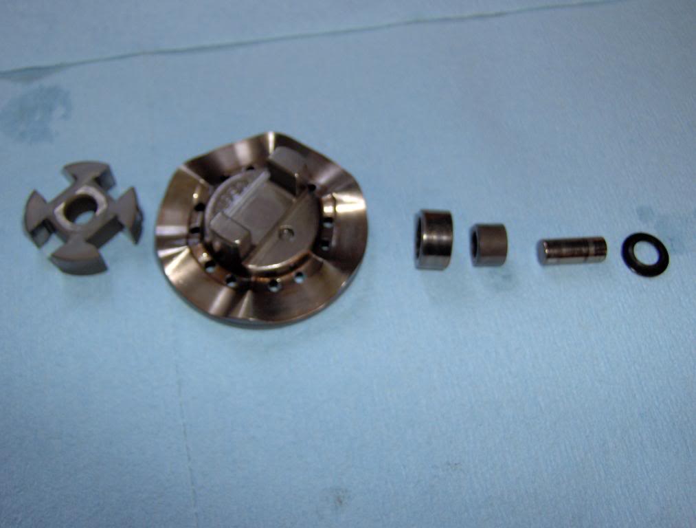
here is all the springs, shim's, pins and goodies. you must keep the pins, shims , and springs that go together together.
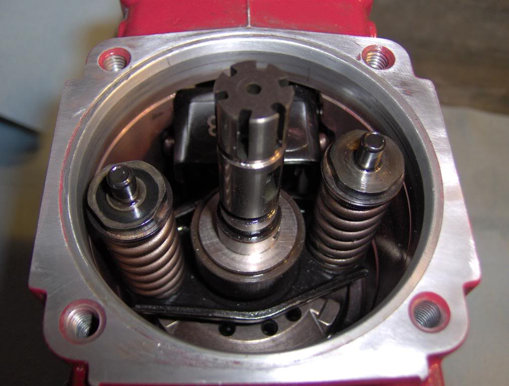
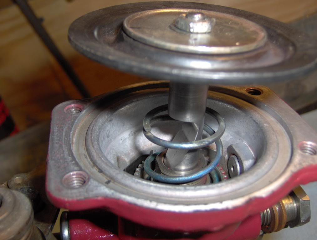
Here you can see where the ball goes into the slide collar on the piston the controls fuel delivery when you remove the piston there is a piece under it that is like a thick washer so keep track of it. the Piston keyed to the cam plate that it sits on.
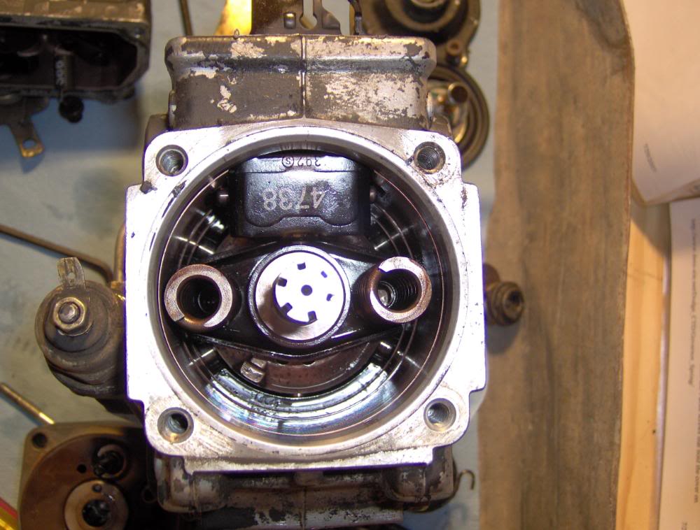
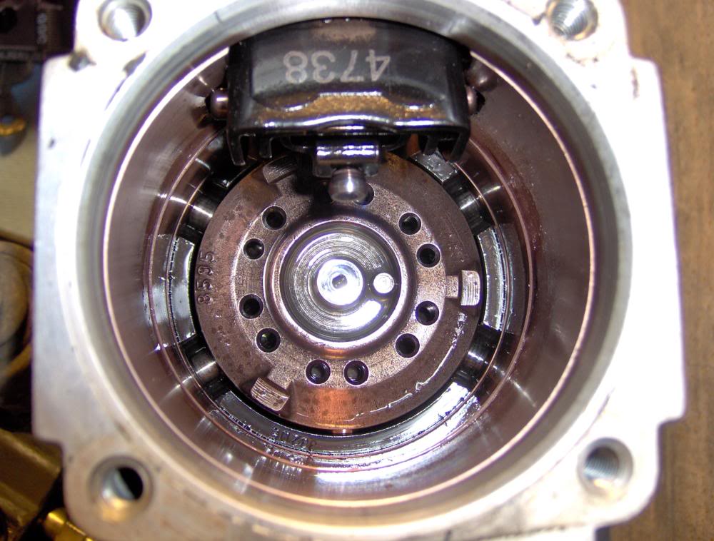
Next remove the Cam Plate then you will see the rollers and + that connect it to the input shaft.
here is all the springs, shim's, pins and goodies. you must keep the pins, shims , and springs that go together together.
Here you can see where the ball goes into the slide collar on the piston the controls fuel delivery when you remove the piston there is a piece under it that is like a thick washer so keep track of it. the Piston keyed to the cam plate that it sits on.
Next remove the Cam Plate then you will see the rollers and + that connect it to the input shaft.
#15
06-12-2008, 10:20 PM
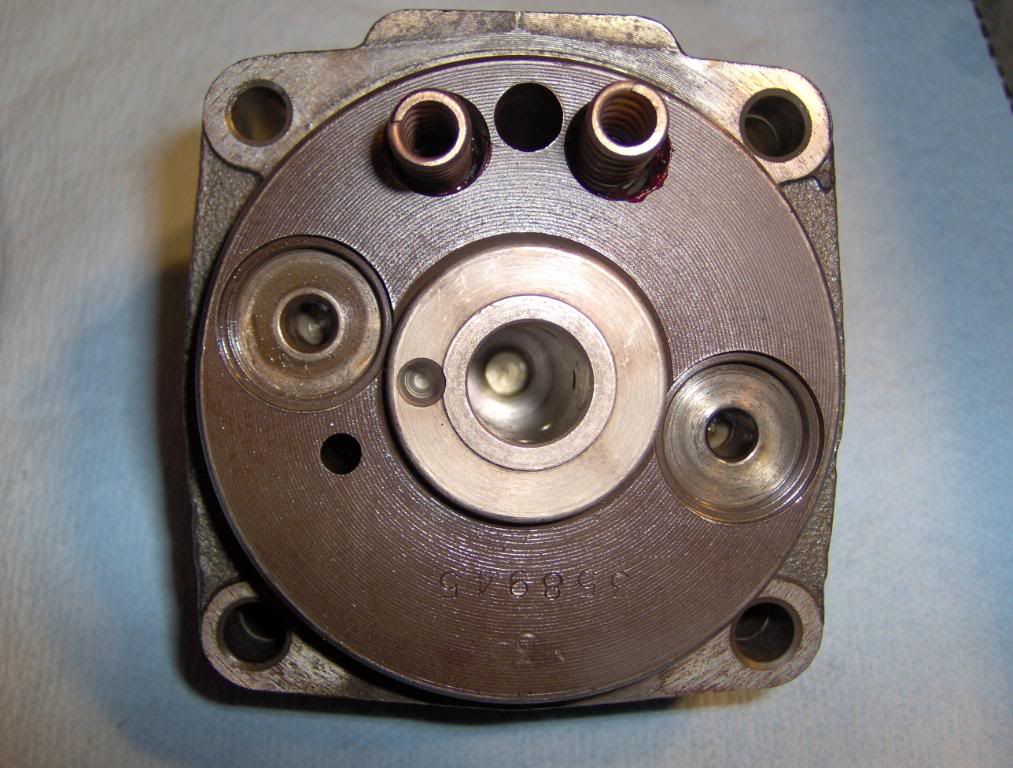
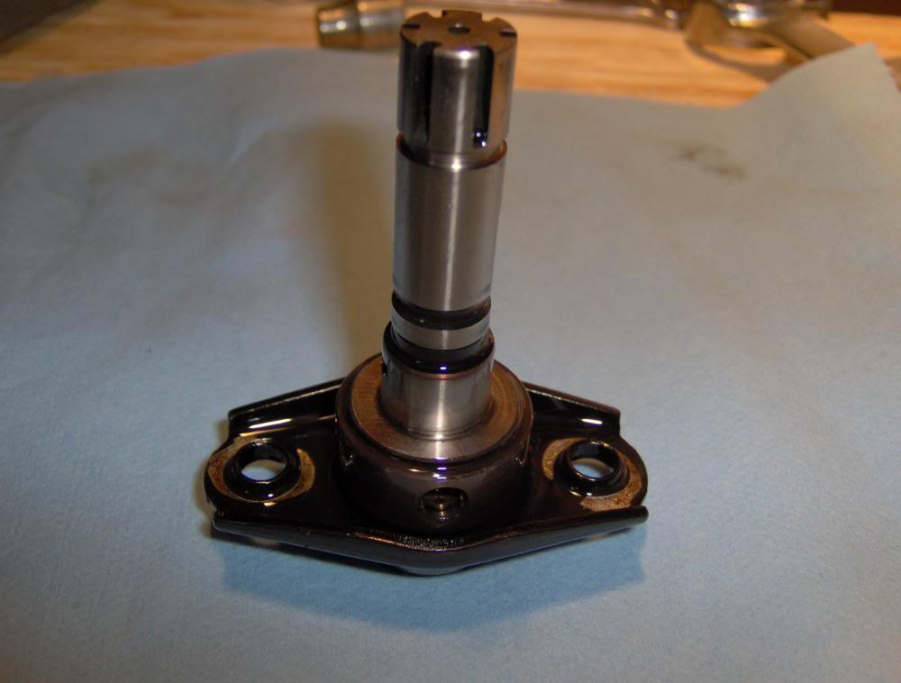
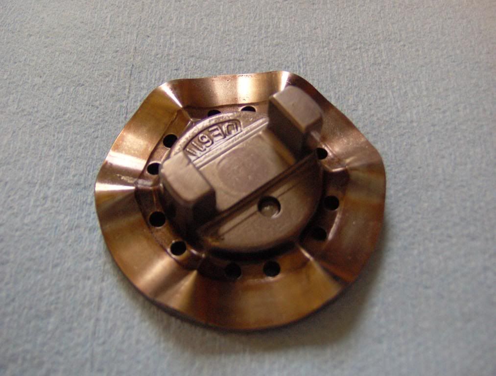
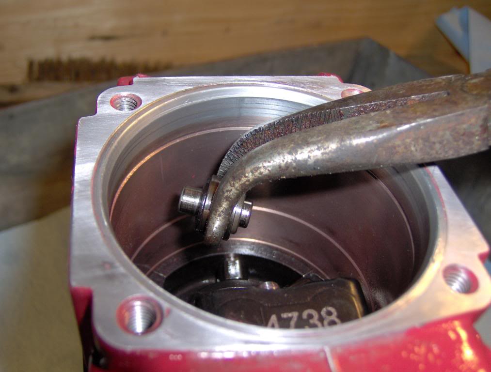
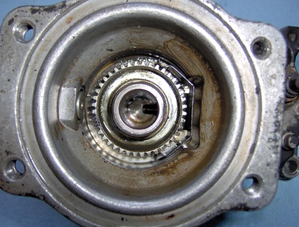
You HAVE to keep the rollers and pins and thrust washers together.
Here you can see were they ride. The KSB pushes the black ring and rotates the rollers and advances your Timing buy making the cam plate ride up on the rollers and stroke the piston sooner in the rotation that pops the injector a few * sooner before TDC.
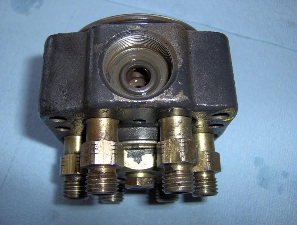
Now lets take the Head apart
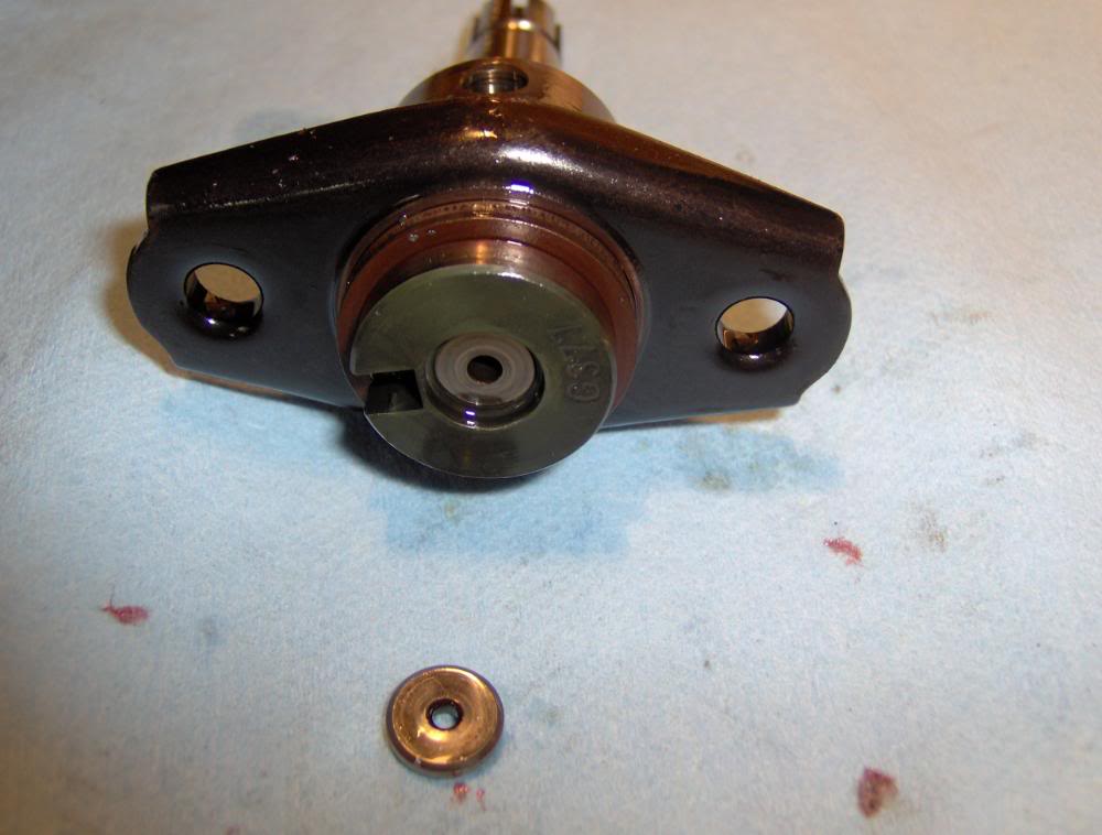
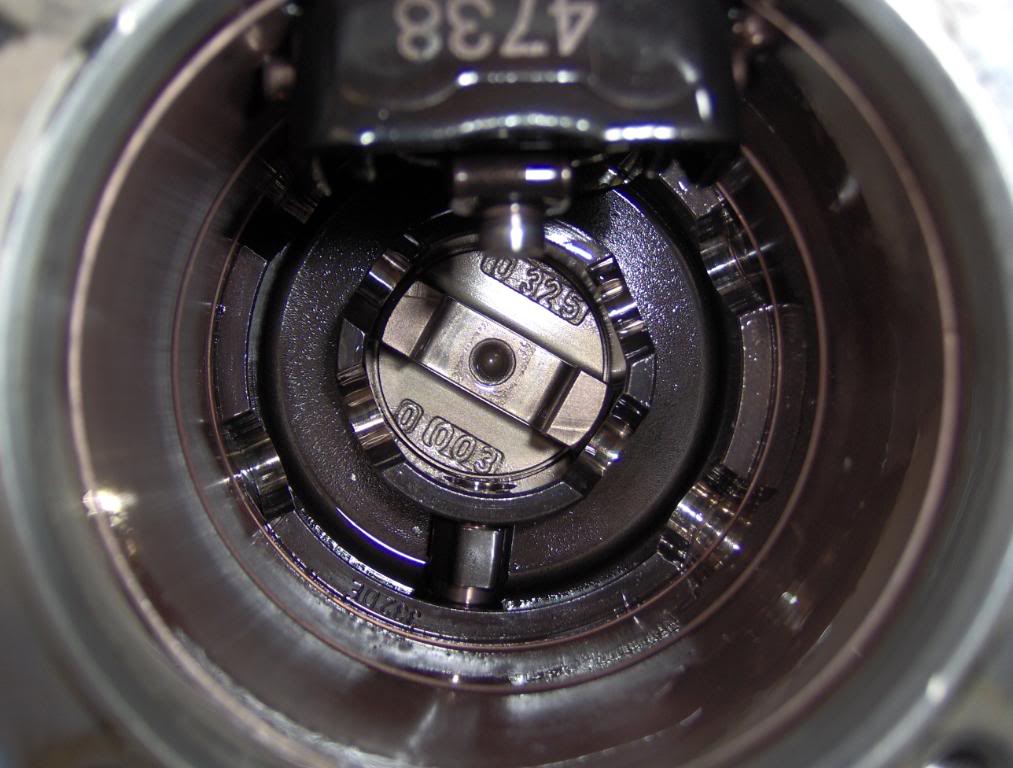
This is how the piston fits in the head and builds the pressure. It also rotates like a distributor and delivers the fuel to the correct cylinder. It strokes every time the the cam plate rides up on the rollers.
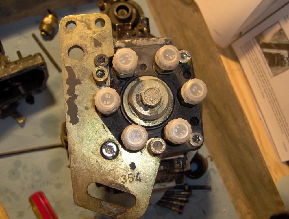
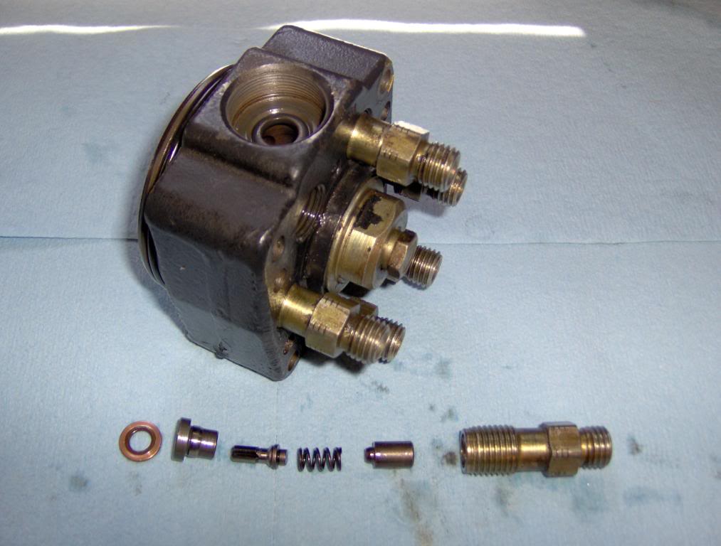
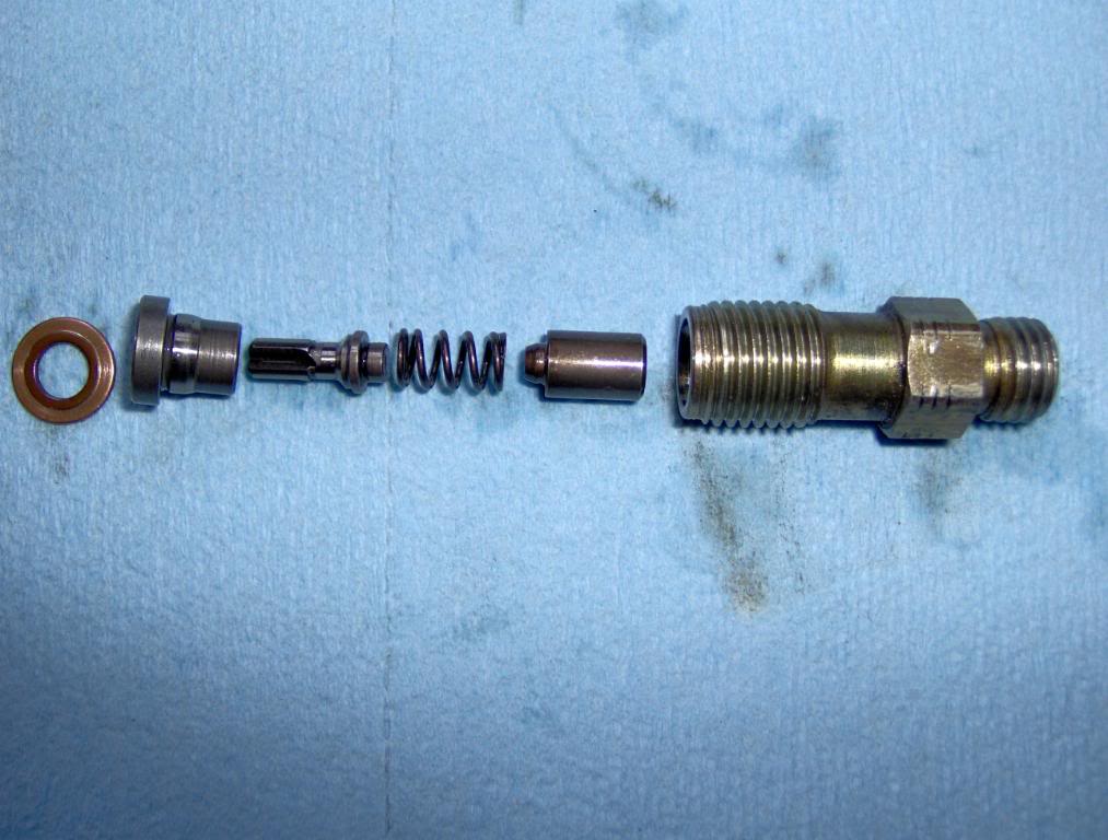
You can remove the Shut down solenoid and replace the o-ring on the tip.
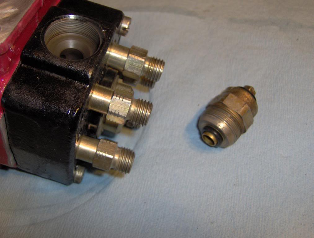
Then you can remove the DV's. YOU MUST KEEP ALL THE PARTS TOGETHER
Here you can see were they ride. The KSB pushes the black ring and rotates the rollers and advances your Timing buy making the cam plate ride up on the rollers and stroke the piston sooner in the rotation that pops the injector a few * sooner before TDC.
Now lets take the Head apart
This is how the piston fits in the head and builds the pressure. It also rotates like a distributor and delivers the fuel to the correct cylinder. It strokes every time the the cam plate rides up on the rollers.
You can remove the Shut down solenoid and replace the o-ring on the tip.
Then you can remove the DV's. YOU MUST KEEP ALL THE PARTS TOGETHER
#16
06-12-2008, 10:21 PM
Well Lets look at some Mods while were in here.[guitar]
Note I am in no way responsible if you do this and burn things up or get a ticket for excessive acceleration [coffee]
Lets start with fuel pins
Fuel pins do the same job as a cam plate on a P-7100 pump. They change how much fuel is delivered in relation ship with boost. As boost builds it pushes down on the diaphragm and pushes the pin down allowing more fuel. There is a spring under it that holds it up and is adjustable and can be set to speed up or slow down the fuel rate in relation to boost. turning the star wheel at the base clock wise will put less pressure on the spring allowing the fuel rate to increase at lower boost = more smoke at lower boost, Counter-clockwise will put more pressure on the spring and slowes the fuel rate at lower boost levels = less smoke at lower boost.
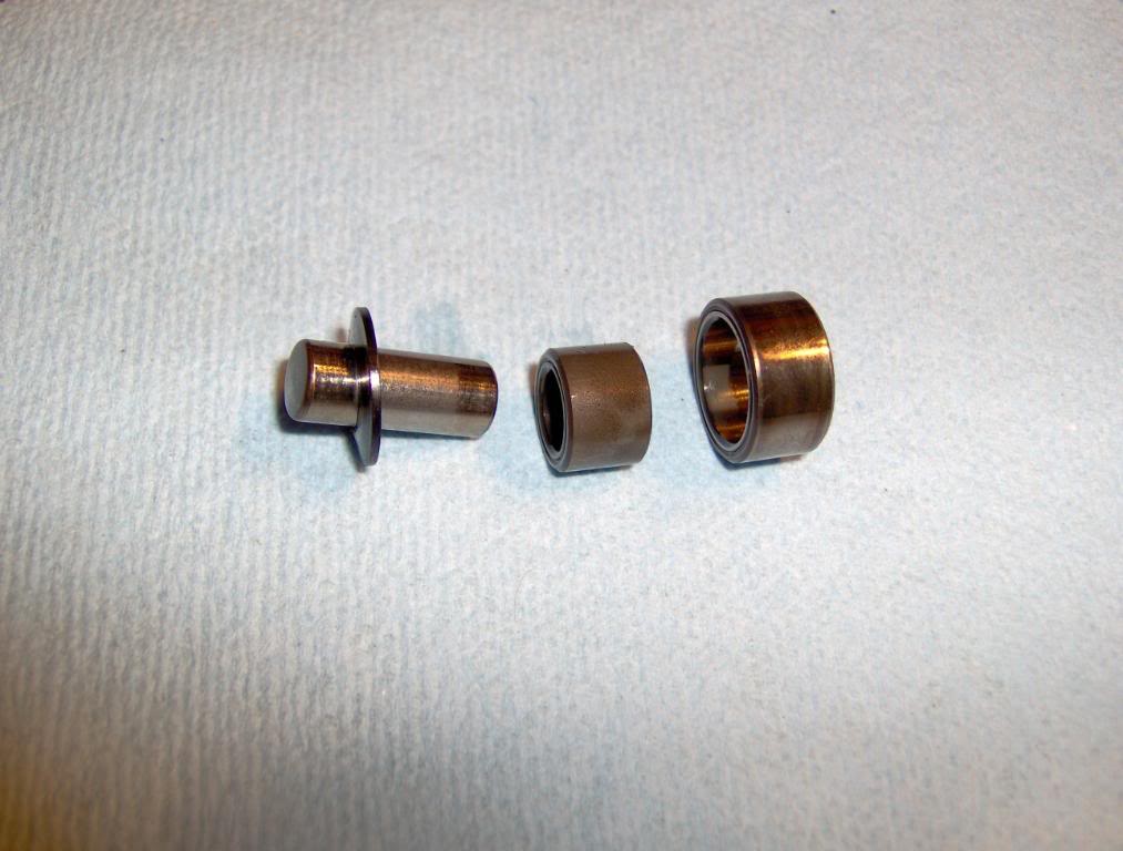
this is the small pin that rides on the fuel pin. It comes out from the front of the pump
the one on the left is a Bully Dog, center is stock, right is Denny T.
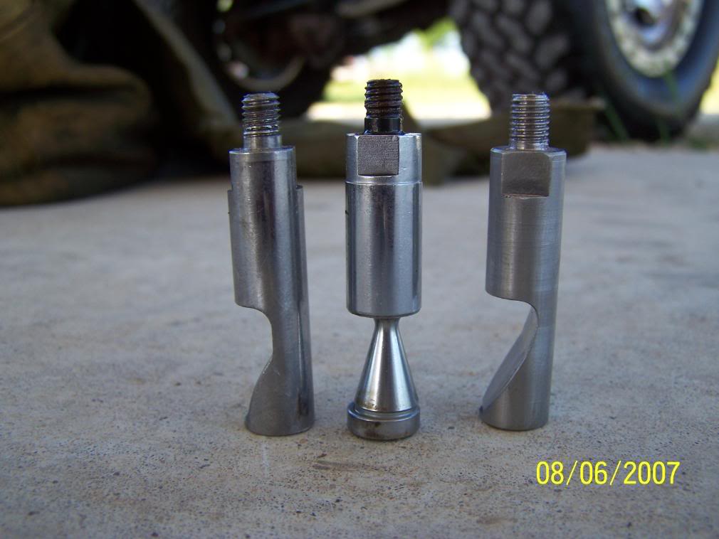
The stock one can bee turned were the eccentric cone is to the rear of the motor thus allowing the pin that rides on it to extend farther out and give more fuel. This is free and will give a noticeable bump in power.
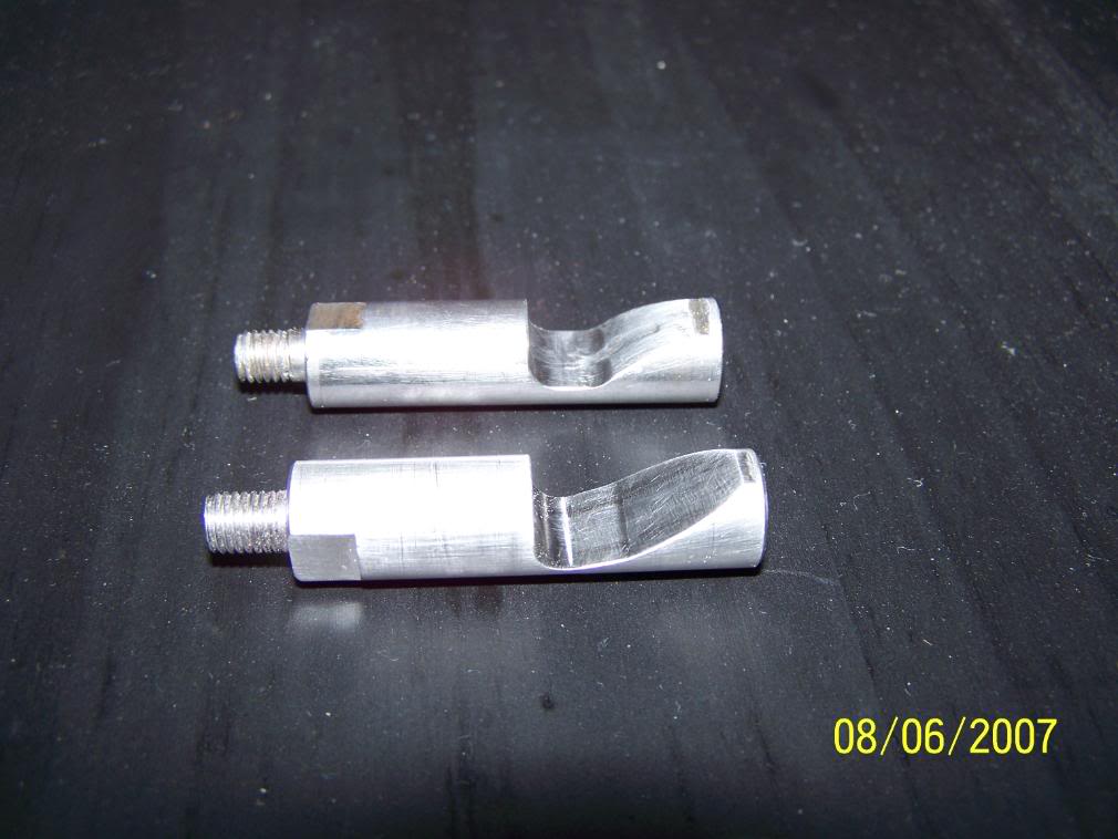
The one on top is a Bully Dog the other is a Denny T. I ran both in my truck and found (like many others) that the Bully Dog made good power but was way to soft and gouged and would stick. The Denny T is maid from very hard SS and will just polish the area and is a lot cheaper. The Denny T pin gives a real boost in power over the Bully Dog and has held up great. DO NOT try to go cheep and make one from mild steel it wont last 100 miles if that[nonono]. There are others out there but I have not tryed them my self.
On the top cover (silver price on top of this pump) there is a Torx head screw that sets the starting depth of the fuel pin at 0psi boost. Ofter called the "Smoke Screw". It can be set deeper CW to give better take off power be for boost comes up but also creates more smoke. It can also be set for less low-no boost fuel and less smoke for pulling and or to compensate for large injectors to keep smoke under control.
Note I am in no way responsible if you do this and burn things up or get a ticket for excessive acceleration [coffee]
Lets start with fuel pins
Fuel pins do the same job as a cam plate on a P-7100 pump. They change how much fuel is delivered in relation ship with boost. As boost builds it pushes down on the diaphragm and pushes the pin down allowing more fuel. There is a spring under it that holds it up and is adjustable and can be set to speed up or slow down the fuel rate in relation to boost. turning the star wheel at the base clock wise will put less pressure on the spring allowing the fuel rate to increase at lower boost = more smoke at lower boost, Counter-clockwise will put more pressure on the spring and slowes the fuel rate at lower boost levels = less smoke at lower boost.
this is the small pin that rides on the fuel pin. It comes out from the front of the pump
the one on the left is a Bully Dog, center is stock, right is Denny T.
The stock one can bee turned were the eccentric cone is to the rear of the motor thus allowing the pin that rides on it to extend farther out and give more fuel. This is free and will give a noticeable bump in power.
The one on top is a Bully Dog the other is a Denny T. I ran both in my truck and found (like many others) that the Bully Dog made good power but was way to soft and gouged and would stick. The Denny T is maid from very hard SS and will just polish the area and is a lot cheaper. The Denny T pin gives a real boost in power over the Bully Dog and has held up great. DO NOT try to go cheep and make one from mild steel it wont last 100 miles if that[nonono]. There are others out there but I have not tryed them my self.
On the top cover (silver price on top of this pump) there is a Torx head screw that sets the starting depth of the fuel pin at 0psi boost. Ofter called the "Smoke Screw". It can be set deeper CW to give better take off power be for boost comes up but also creates more smoke. It can also be set for less low-no boost fuel and less smoke for pulling and or to compensate for large injectors to keep smoke under control.
#17
06-12-2008, 10:22 PM
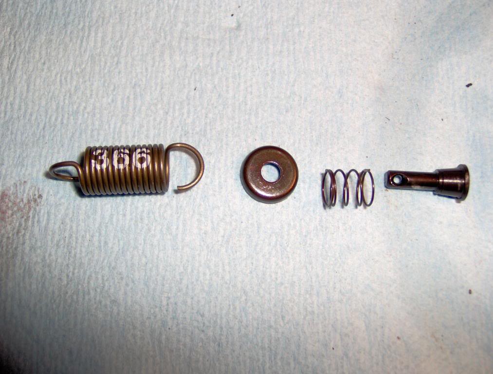
GSK = 366 Spring = 3200 Governor spring kit
4200 Kit also available.
Starting with throttle linkage and springs removed ( shown how to earlyer) not required if not replacing the shaft seal
Remove the 4 Allen head bolts that holds the top to the main case.
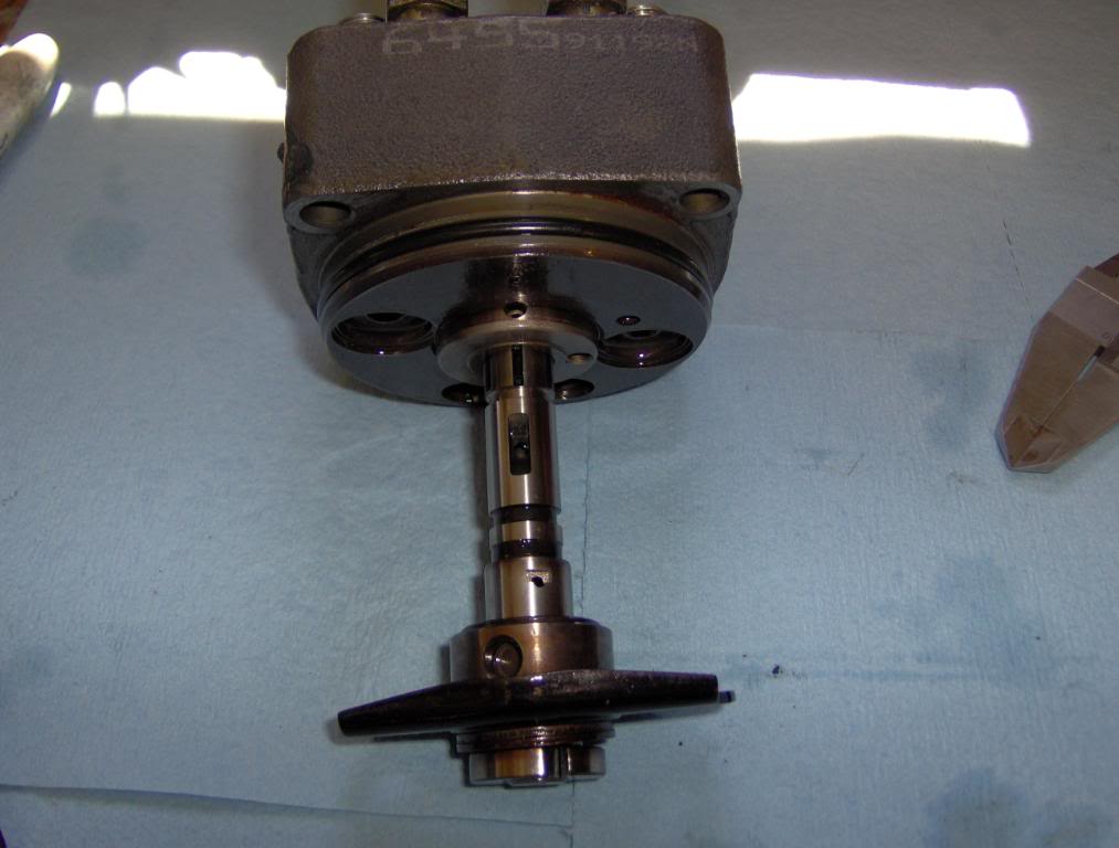
Slowly lift the top from the pump, you may hear a clock as the lever comes off of the full fuel screw but that's fine. The spring and other parts will not fly out just go slow. as it comes up you will See the spring and can remove it form the throttle rod and hold it while you set the top aside.
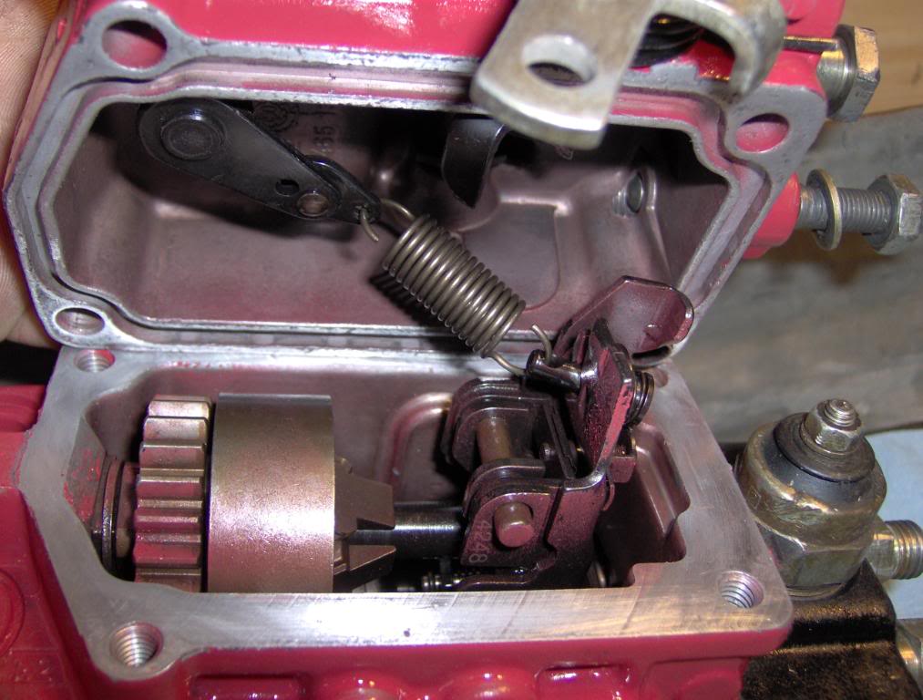
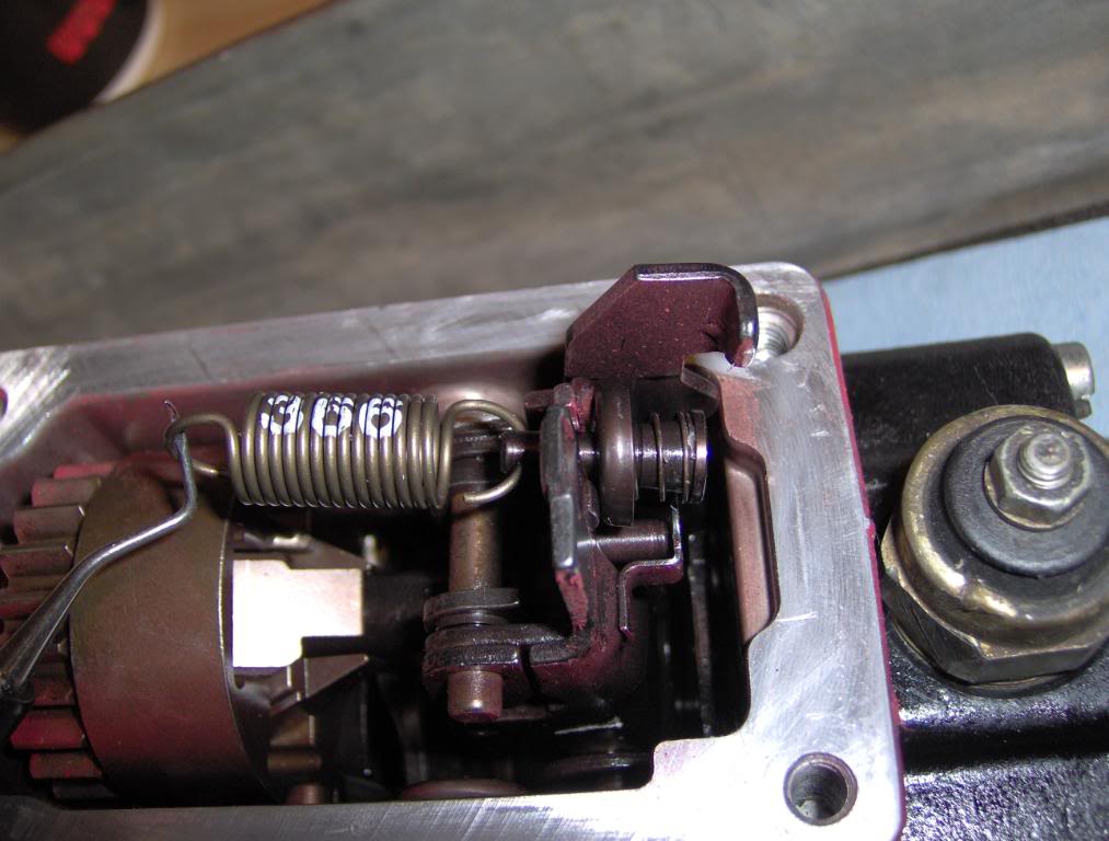
Then you can hold the "Top Hat" (pin with spring and washer that is connected to the other end of the gov spring) and remove the gov spring then the top hat.
This is how all the parts go together. Make sure you have them all.
while you are here you can grind the AFC lever to alow more fuel just like the fuel pin. This is not reversable and should be left to guys that want all out performance!! You can not go back
The pin is pointed at the AFC lever and can be ground down to alow for more fuel. The more you grind the more fuel you get to a point. Do at your own risk. The other is the Kill lever DO NOT cut it.
Installing of the new spring is just reverse of removing the old one.
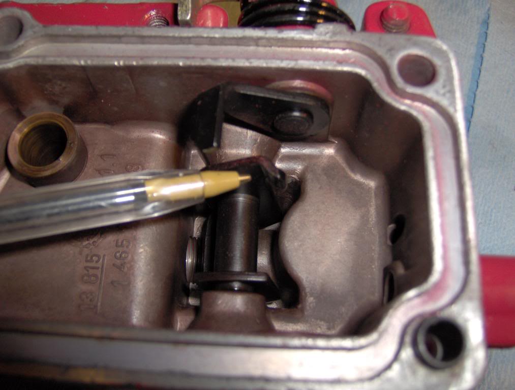
The lever behind the gov spring is the one that the Full fuel screw pushes on and can be pulled toward the front of the pump with a small wire or string to clear the screw as the top is placed back on the pump if the screw was left in place. As you set the top on you can then remove the string or wire and finish installing the top. One other way is to note the depth of the full fuel screw and back it out till the tip is flush with the inside of the cover, as you cam see , this will alow the cover to set on the pump with no probs and then it can be placed back to the previously noted depth.
When you have it all back together remove the intake tube from the turbo and have a bord or some thing solid that you can place over the intake of the turbo to cut off the air and kill the motor incase of runaway.
DO NOT USE YOUR HAND
4200 Kit also available.
Starting with throttle linkage and springs removed ( shown how to earlyer) not required if not replacing the shaft seal
Remove the 4 Allen head bolts that holds the top to the main case.
Slowly lift the top from the pump, you may hear a clock as the lever comes off of the full fuel screw but that's fine. The spring and other parts will not fly out just go slow. as it comes up you will See the spring and can remove it form the throttle rod and hold it while you set the top aside.
Then you can hold the "Top Hat" (pin with spring and washer that is connected to the other end of the gov spring) and remove the gov spring then the top hat.
This is how all the parts go together. Make sure you have them all.
while you are here you can grind the AFC lever to alow more fuel just like the fuel pin. This is not reversable and should be left to guys that want all out performance!! You can not go back
The pin is pointed at the AFC lever and can be ground down to alow for more fuel. The more you grind the more fuel you get to a point. Do at your own risk. The other is the Kill lever DO NOT cut it.
Installing of the new spring is just reverse of removing the old one.
The lever behind the gov spring is the one that the Full fuel screw pushes on and can be pulled toward the front of the pump with a small wire or string to clear the screw as the top is placed back on the pump if the screw was left in place. As you set the top on you can then remove the string or wire and finish installing the top. One other way is to note the depth of the full fuel screw and back it out till the tip is flush with the inside of the cover, as you cam see , this will alow the cover to set on the pump with no probs and then it can be placed back to the previously noted depth.
When you have it all back together remove the intake tube from the turbo and have a bord or some thing solid that you can place over the intake of the turbo to cut off the air and kill the motor incase of runaway.
DO NOT USE YOUR HAND
#18
06-12-2008, 10:23 PM
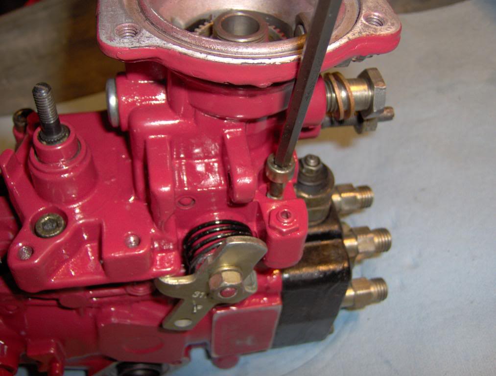
Now for the Full Fuel screw
This will really wake things up.
Befor you start remove the intake tube from the turbo and get some thing hard and flat that can be used to cut off the air and kill the motor in case of runaway.
DO NOT use your hand it WILL get pulled into the turbo
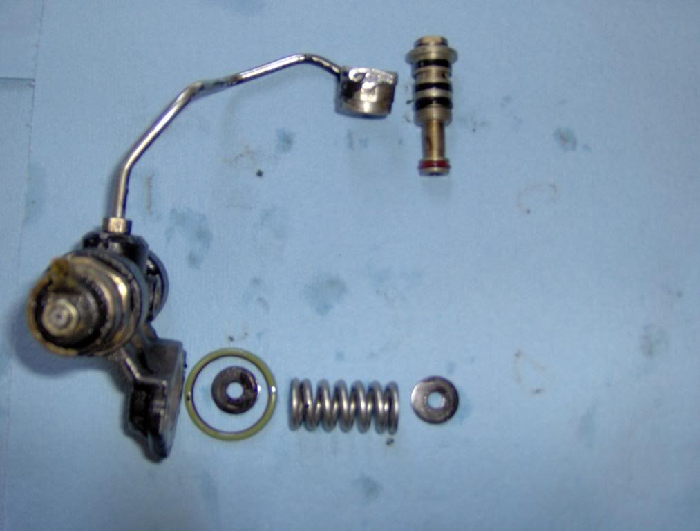
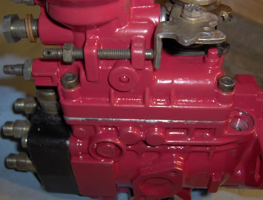
The one I am talking about is the one on the rear of the pump nearest to the shut down solenoid. If your pump has never been messed with it will have a small collar that is tack welded to the screw and will need to be removed to alow for moor adjustment. You can mark the stock depth of the screw and remove it and then remove the collar and reinstall it to the stock depth.
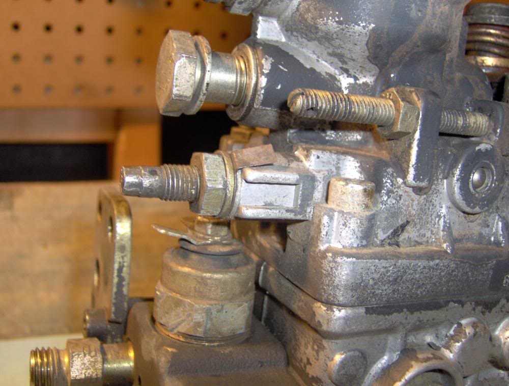
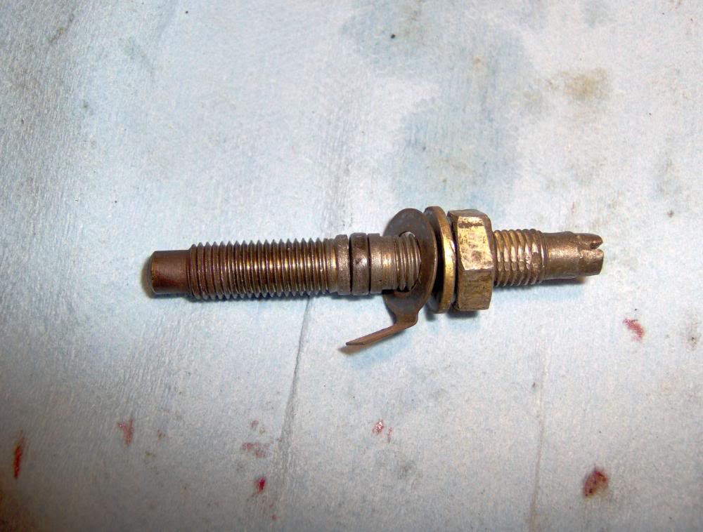
Here is the screw with the collar removed
Most guys will go 2 turns clockwise from stock and are very happy. If you want to get all you can out of your pump I start the truck with it in the stock position. Then using a 6mm socket and ( or flat tip screwdriver) a extension slowly turn it CW. Go about 1/4 turn at a time after 2 turns and rev the engine a few 100 RPM and then release it fast and make sure that it idles down as fast as it use to. Repeat this till you get to the point were it is slow to idle back down or the RPM's hover or stick. Now you are close to runaway so back off till it idles down like it should ( about 1/4-1/2 turn) and lock the jam nut. Try it a few times and run it to WOT and make sure that it will idle back down as soon as you release the throttle.
Your throttle will be a few 100 RPM higher than stock when done. You need to get to the low idle screw and loosen the jam nut and turn it counter clock wise to get it back to about stock RPM then tighten the jam nut.
This will really wake things up.
Befor you start remove the intake tube from the turbo and get some thing hard and flat that can be used to cut off the air and kill the motor in case of runaway.
DO NOT use your hand it WILL get pulled into the turbo
The one I am talking about is the one on the rear of the pump nearest to the shut down solenoid. If your pump has never been messed with it will have a small collar that is tack welded to the screw and will need to be removed to alow for moor adjustment. You can mark the stock depth of the screw and remove it and then remove the collar and reinstall it to the stock depth.
Here is the screw with the collar removed
Most guys will go 2 turns clockwise from stock and are very happy. If you want to get all you can out of your pump I start the truck with it in the stock position. Then using a 6mm socket and ( or flat tip screwdriver) a extension slowly turn it CW. Go about 1/4 turn at a time after 2 turns and rev the engine a few 100 RPM and then release it fast and make sure that it idles down as fast as it use to. Repeat this till you get to the point were it is slow to idle back down or the RPM's hover or stick. Now you are close to runaway so back off till it idles down like it should ( about 1/4-1/2 turn) and lock the jam nut. Try it a few times and run it to WOT and make sure that it will idle back down as soon as you release the throttle.
Your throttle will be a few 100 RPM higher than stock when done. You need to get to the low idle screw and loosen the jam nut and turn it counter clock wise to get it back to about stock RPM then tighten the jam nut.
#19
06-13-2008, 12:07 AM
 WoW......great detailed instruction!


