
Auto to NV4500 Conversion

So Im posting a build thread for my recent 46RH to NV4500 Conversion for anyone that may be interested in a similar swap. To start off, here's the list of specific things the swap required:
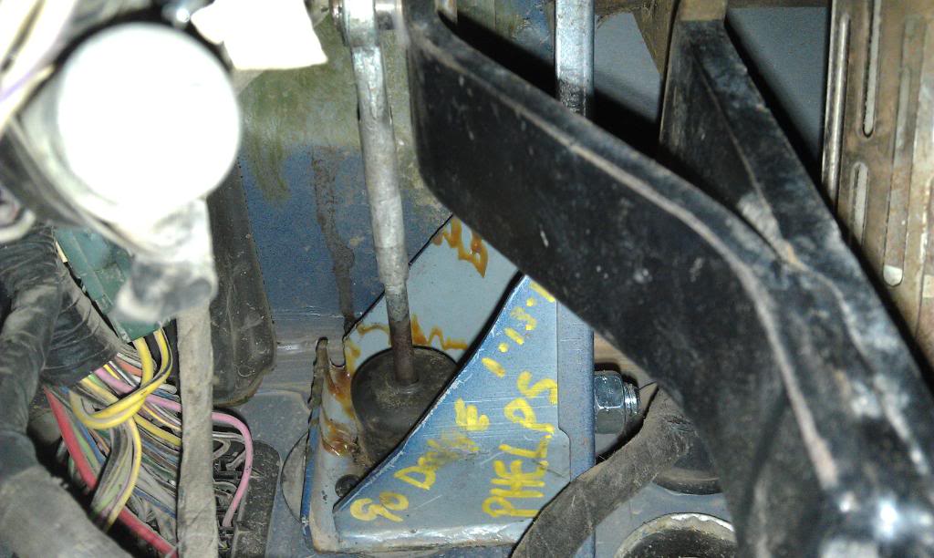
These first section of things I got from Holst Truck Parts in Ucon Idaho (holsttruck.com). They sent me a pallet with all of these things already collected and If you don't have the parts already from somewhere else, I strongly recommend these guys at Holst Truck Parts. I dealt with the guy named Phelps (ext. #5 on their answering machine) and they were very knowledgeable and good to deal with.
o Dodge fitted NV4500 Transmission
o Bell housing (NV4500 donor)
o Engine block adapter plate (NV4500 donor)
o Pedal set from a first gen with a getrag
o Clutch Master Cylinder and reservoir for a first gen with a Getrag
o Hose for between Slave and master Cylinder
o Starter (NV4500 donor) PN: 4N-6428, $317.43 (for new)
o Slave Cylinder for either manual PN: 73314 $154.84
This second section I got from elsewhere:
o Boots (5 speed Shifter lever and 4x4 shifter lever)
o Clutch, TO Bearing & Flywheel
o New (adjusted length) driveshafts, Mine turned out to be 4” different length.
o 23 – 29 spline adapter for transfercase (or a 29 spline input, right side front shaft transfercase). Second Hand Smoke Diesel (Second Hand Smoke Diesel Performance) sells the adapter for $220 with a $70 core on the factory one so you end up $150 poorer.
o Hose and fittings to bypass Liquid cooled Tranny cooler(total of $34.24)
o 3quarts of 75W-90 or some gear oil for the Transfercase
o 4 Quarts of fancy gear oil (required for the NV4500) $25/quart and can be purchased from either GM or DODGE dealerships, maybe elsewhere.
Recommended:
1. Rear main seal PN: BS40633, $73.94
2. Transfercase input seal, Napa couldn’t find the correct double lipped one so I ended up buying two single lip seals by dimenstion that would fit and putting them back to back. I lost the PN but the dimensions that I got them from are the 1.982 inch OD and the 1.373 inch ID, both of which were measured with micrometers so they should be accurate to the thousandth.
3. Front and rear Transfercase output seals PN:18752 ($34.13) and 21213 ($20.09), respectively.
4. I did the oilpan gasket because mine was leaking slightly and it looks like you’d have to pull the transmission and lift the motor out part way to do that so it may be the opportune time.PN: OS34102 ($30.58)
---AutoMerged DoublePost---
So here's with the driveshafts removed and the Transfercase skids removed. I just want to say at this point that I love these trucks! Everything up to the back of the motor is all standard, and Its really all like 4 sizes including 9/16, 5/8, 11/16, 3/4, and some 13/16 I believe.
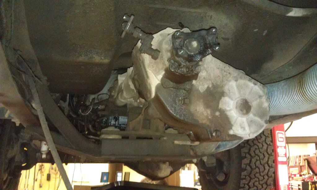
Here's with the transfercase removed.
Ok, at this point there are a mess of Tranny lines to deal with. On mine there were 2 lines that run from the tranny to the liquid cooled tranny cooler on the passenger side of the block (pictured later), 2 lines that run to the little tranny cooler in front of the radiator, and 2 hoses that run to the huge fan cooled cooler under the passenger rear seat. For ease of removal at the time I cut the two that run to the Liquid cooler as they ran under the bellhousing because I couldn't reach the fittings on the cooler from the bottom and I wasn't going to re-use the lines or anything anyway so I had no reason not to.
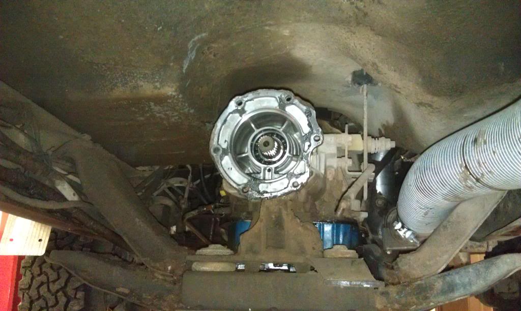
So the tranny is out!
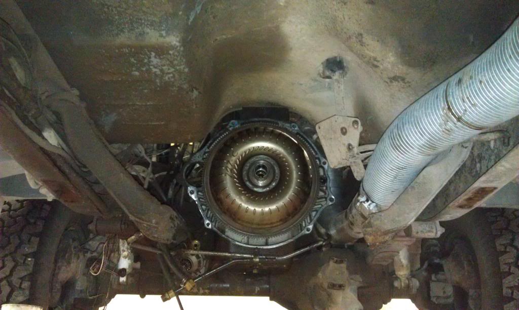
So this next part took me a bit to figure out but it turned out to be just as expected: way easier than I was making it. At first I tried to pull the Torque converter bolts with a wrench from the bottom but the bolts would back into the Block Adapter plate before i could get them out. Turns out there is an access panel on the block adapter plate that has two bolts to get to those bolts.
From the Front:
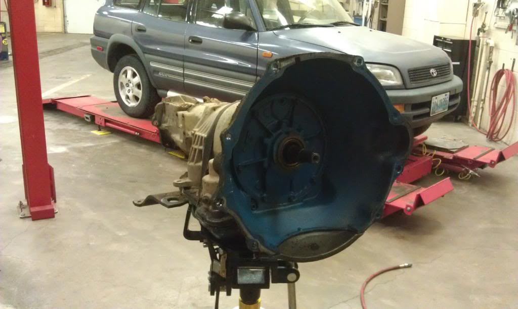
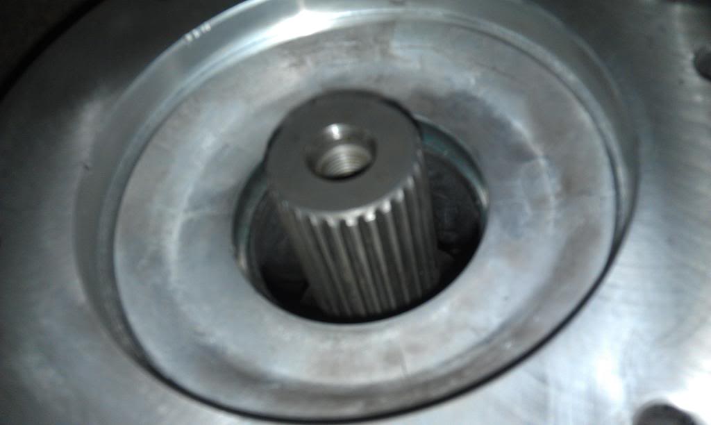
And with the torque converter and flex plate removed:
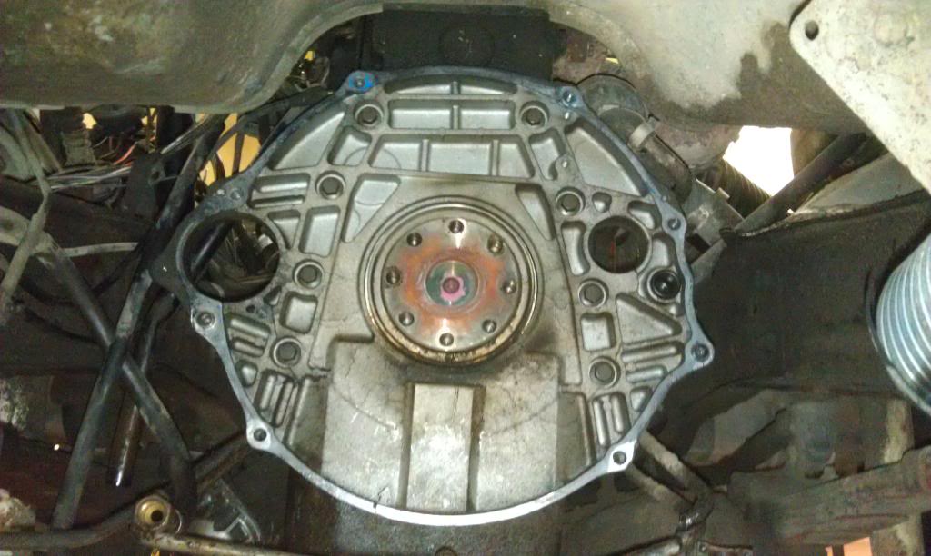
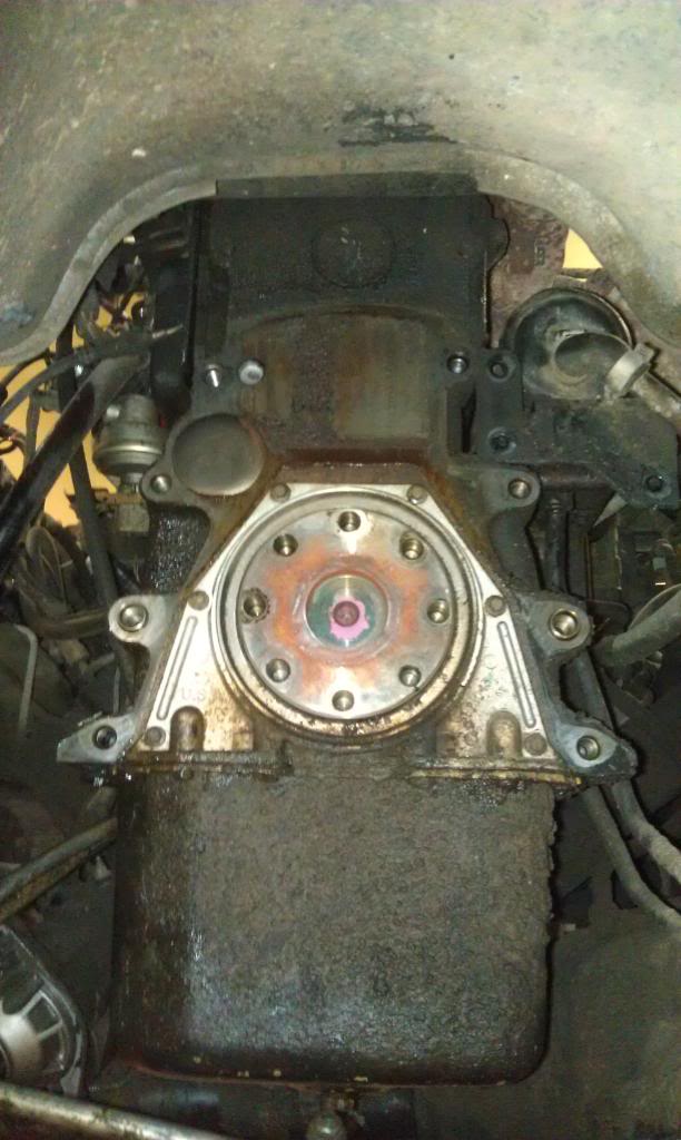
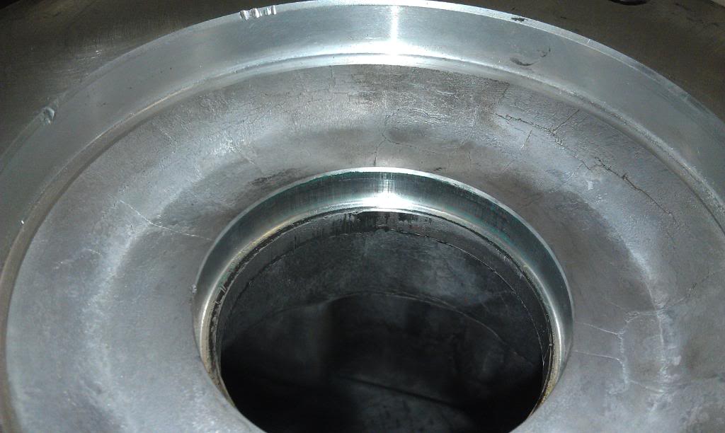
And with the Block adapter plate removed:

---AutoMerged DoublePost---
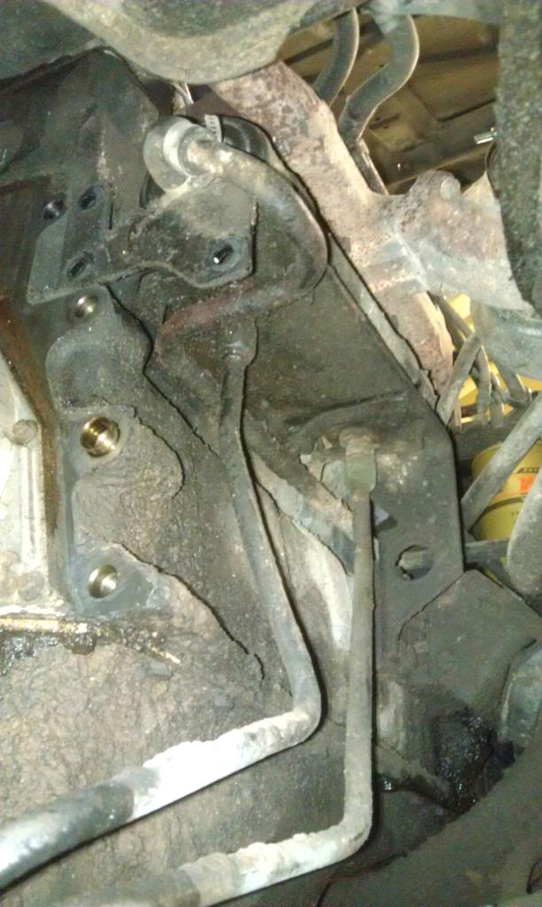
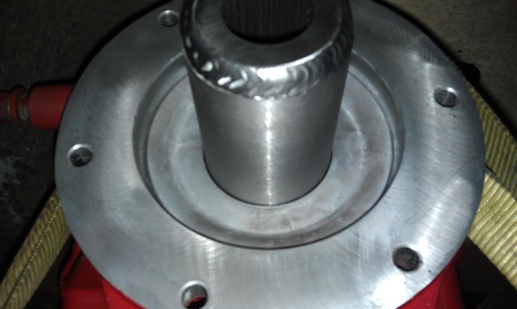
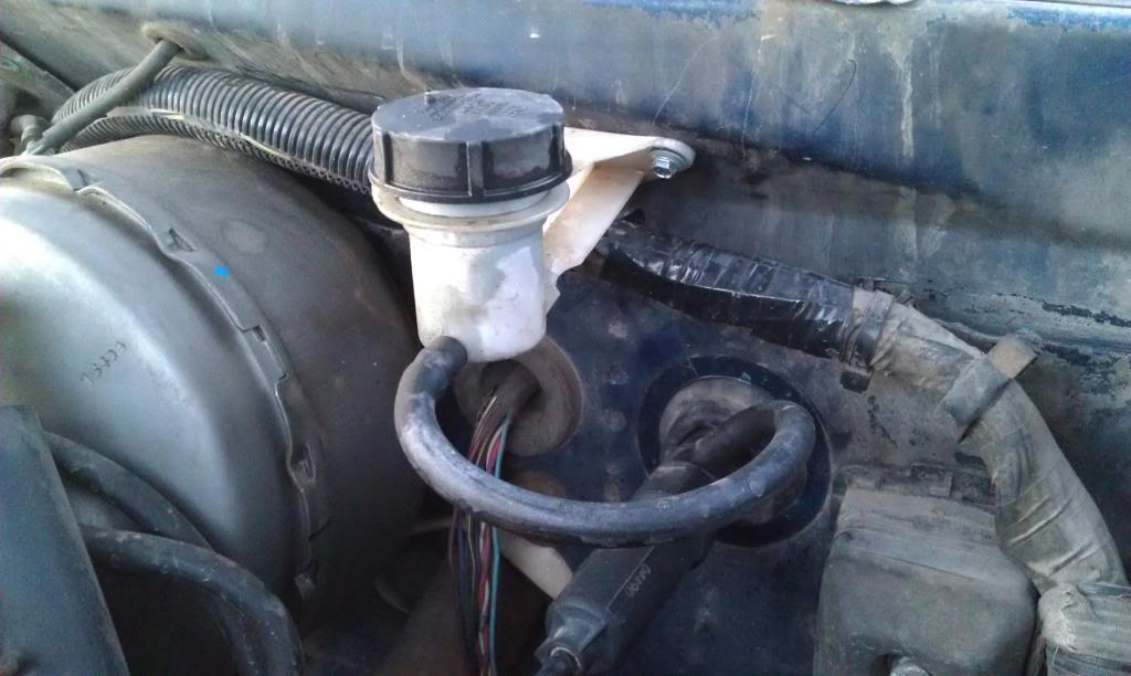
So here's a picture from the bottom of the Liquid cooled transmission cooler. it has a hose running out of either end that run to the side of the block up front and the 2 lines coming out of the bottom are ATF. The platform it sits on bolts to the Block adapter plate and the block itself.
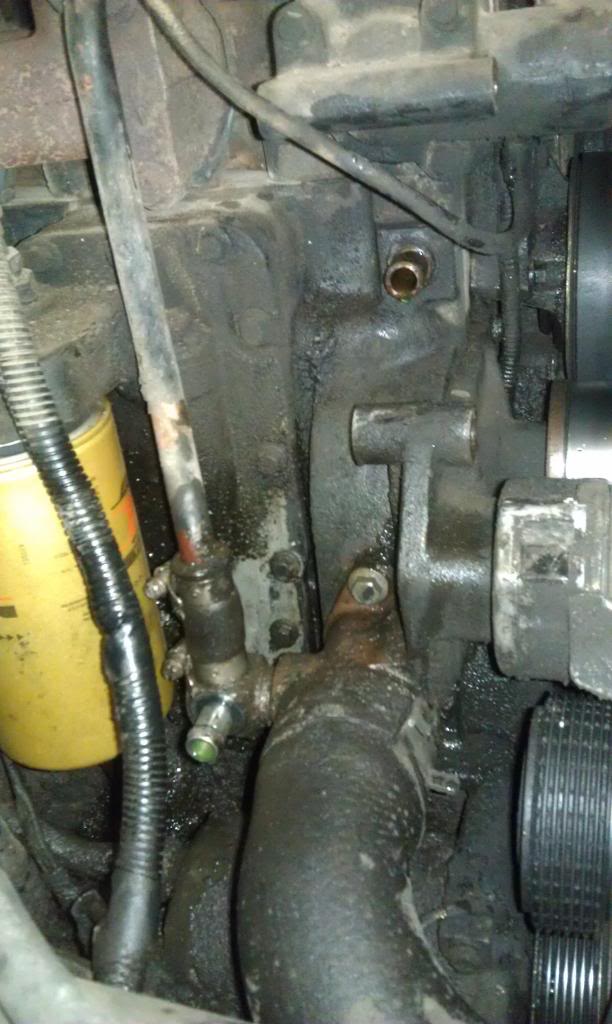
And here are the two ports that the coolant runs from the block to the liquid cooler with the hoses removed. The alternator is also removed in this picture, it would sit in front of the upper port.
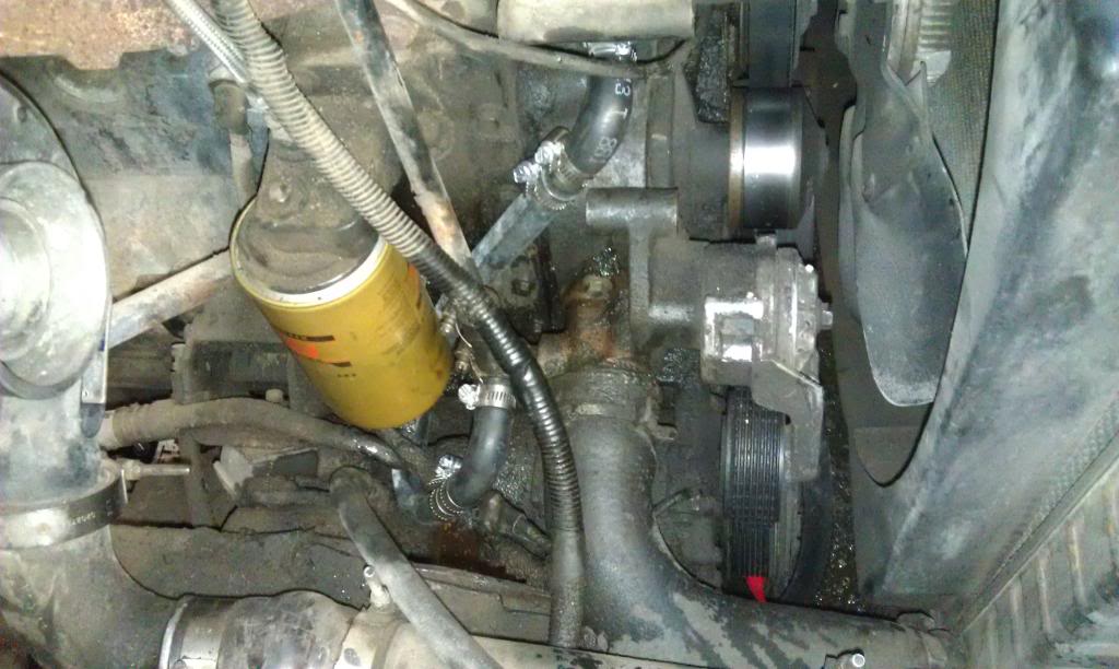
And here is the aforementioned bypass of the cooler. The hose has to include a pre-bent 90 on the top becuase of how close the alternator sits to the block, and I used exactly 18" of hose and another 90 on the other end and two couplers to achieve the desired route that I deemed best based on changing of the oil filter in the future and not having it have any pressure on anything that would cause rubbing of a hole in the hose in the long run.
These first section of things I got from Holst Truck Parts in Ucon Idaho (holsttruck.com). They sent me a pallet with all of these things already collected and If you don't have the parts already from somewhere else, I strongly recommend these guys at Holst Truck Parts. I dealt with the guy named Phelps (ext. #5 on their answering machine) and they were very knowledgeable and good to deal with.
o Dodge fitted NV4500 Transmission
o Bell housing (NV4500 donor)
o Engine block adapter plate (NV4500 donor)
o Pedal set from a first gen with a getrag
o Clutch Master Cylinder and reservoir for a first gen with a Getrag
o Hose for between Slave and master Cylinder
o Starter (NV4500 donor) PN: 4N-6428, $317.43 (for new)
o Slave Cylinder for either manual PN: 73314 $154.84
This second section I got from elsewhere:
o Boots (5 speed Shifter lever and 4x4 shifter lever)
o Clutch, TO Bearing & Flywheel
o New (adjusted length) driveshafts, Mine turned out to be 4” different length.
o 23 – 29 spline adapter for transfercase (or a 29 spline input, right side front shaft transfercase). Second Hand Smoke Diesel (Second Hand Smoke Diesel Performance) sells the adapter for $220 with a $70 core on the factory one so you end up $150 poorer.
o Hose and fittings to bypass Liquid cooled Tranny cooler(total of $34.24)
o 3quarts of 75W-90 or some gear oil for the Transfercase
o 4 Quarts of fancy gear oil (required for the NV4500) $25/quart and can be purchased from either GM or DODGE dealerships, maybe elsewhere.
Recommended:
1. Rear main seal PN: BS40633, $73.94
2. Transfercase input seal, Napa couldn’t find the correct double lipped one so I ended up buying two single lip seals by dimenstion that would fit and putting them back to back. I lost the PN but the dimensions that I got them from are the 1.982 inch OD and the 1.373 inch ID, both of which were measured with micrometers so they should be accurate to the thousandth.
3. Front and rear Transfercase output seals PN:18752 ($34.13) and 21213 ($20.09), respectively.
4. I did the oilpan gasket because mine was leaking slightly and it looks like you’d have to pull the transmission and lift the motor out part way to do that so it may be the opportune time.PN: OS34102 ($30.58)
---AutoMerged DoublePost---
So here's with the driveshafts removed and the Transfercase skids removed. I just want to say at this point that I love these trucks! Everything up to the back of the motor is all standard, and Its really all like 4 sizes including 9/16, 5/8, 11/16, 3/4, and some 13/16 I believe.
Here's with the transfercase removed.
Ok, at this point there are a mess of Tranny lines to deal with. On mine there were 2 lines that run from the tranny to the liquid cooled tranny cooler on the passenger side of the block (pictured later), 2 lines that run to the little tranny cooler in front of the radiator, and 2 hoses that run to the huge fan cooled cooler under the passenger rear seat. For ease of removal at the time I cut the two that run to the Liquid cooler as they ran under the bellhousing because I couldn't reach the fittings on the cooler from the bottom and I wasn't going to re-use the lines or anything anyway so I had no reason not to.
So the tranny is out!
So this next part took me a bit to figure out but it turned out to be just as expected: way easier than I was making it. At first I tried to pull the Torque converter bolts with a wrench from the bottom but the bolts would back into the Block Adapter plate before i could get them out. Turns out there is an access panel on the block adapter plate that has two bolts to get to those bolts.
From the Front:
And with the torque converter and flex plate removed:
And with the Block adapter plate removed:
---AutoMerged DoublePost---
So here's a picture from the bottom of the Liquid cooled transmission cooler. it has a hose running out of either end that run to the side of the block up front and the 2 lines coming out of the bottom are ATF. The platform it sits on bolts to the Block adapter plate and the block itself.
And here are the two ports that the coolant runs from the block to the liquid cooler with the hoses removed. The alternator is also removed in this picture, it would sit in front of the upper port.
And here is the aforementioned bypass of the cooler. The hose has to include a pre-bent 90 on the top becuase of how close the alternator sits to the block, and I used exactly 18" of hose and another 90 on the other end and two couplers to achieve the desired route that I deemed best based on changing of the oil filter in the future and not having it have any pressure on anything that would cause rubbing of a hole in the hose in the long run.
Last edited by That93Guy; Feb 24, 2012 at 01:59 AM. Reason: Automerged Doublepost
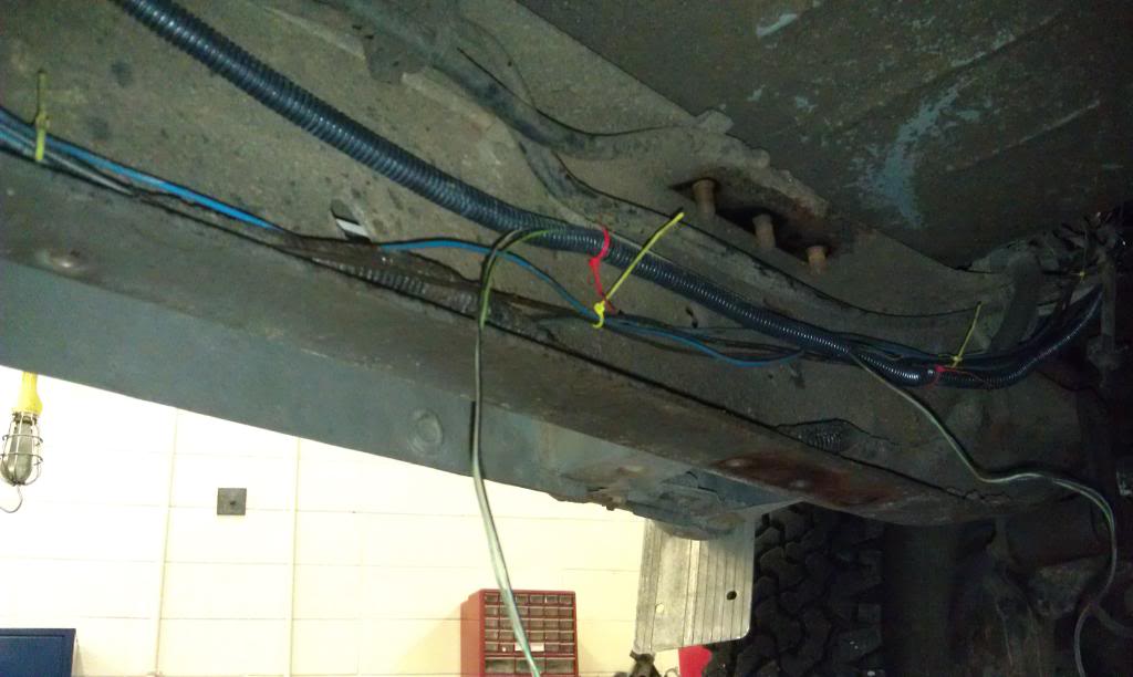
Ok now to Jump to wiring for a bit... Of these first three wires, the left (big round three wire) plug is for the neutral/park safety switch. This set of three includes a white with a brown stripe wire that will be the one that we will be grounding to allow the truck to start at some point. One of the other two is the Reverse light plug but unfortunately it is the wrong type of plug for the new transmission so it will require replacement if you want the reverse lights to kick on. The other wire runs to a temp sender on one of the tranny's old lines. These wires I cut off just as they emerged from the bundle near the brake booster.
These other two wires are much longer and run to the transfercase for the speedo sender and the 4WD indicator. These I wrapped in corregated tubing and left otherwise alone.
The next two pics are of the oil-pan gasket change. My gasket appeared to be leaking so I decided to replace it when I had the truck apart anyway, and it turns out that you have to lift the motor a couple inches to clear the crossmember with the pan. The two bottom-most bolts on the motor mounts (the mostly vertical ones with the 19mm nuts) fit in oblong holes which make the motor easiest to sit back down in the right place. When sitting the motor back down, in my case the passenger side had to be at the top of the hole and the driver side down for the motor to sit level and for the starter to clear the framerail because the starter from the 2nd gen has a different orientation.
And my shiny repainted oilpan:
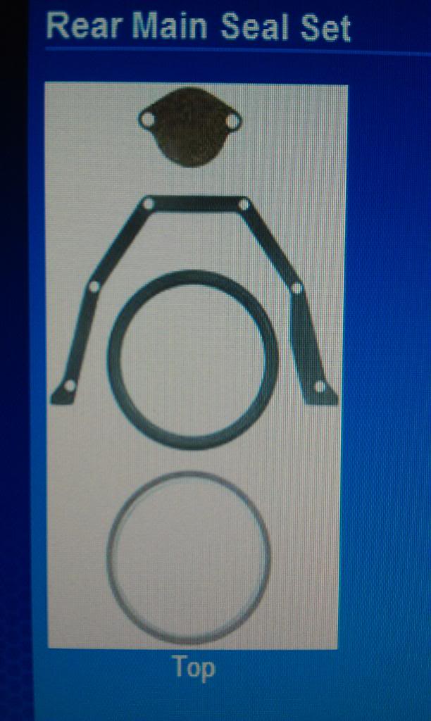
The next couple pics are of the rear main seal replacement that I decided to do because it was cheap and now would be the time to do it. This is the seal and gasket kit I bought. :
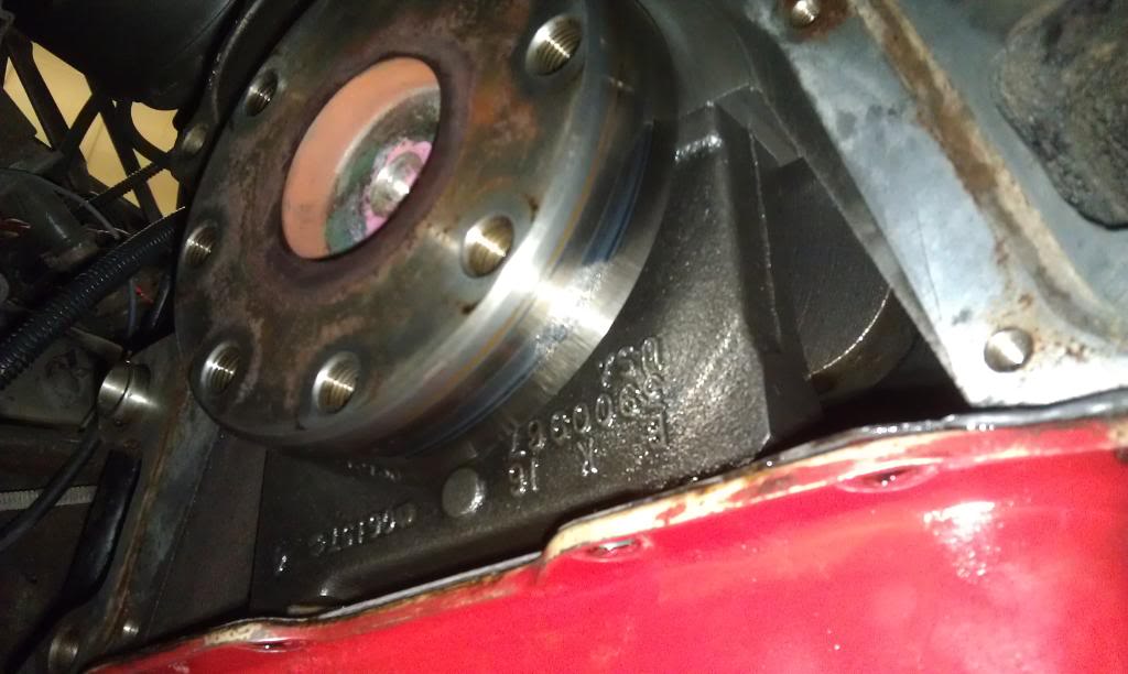
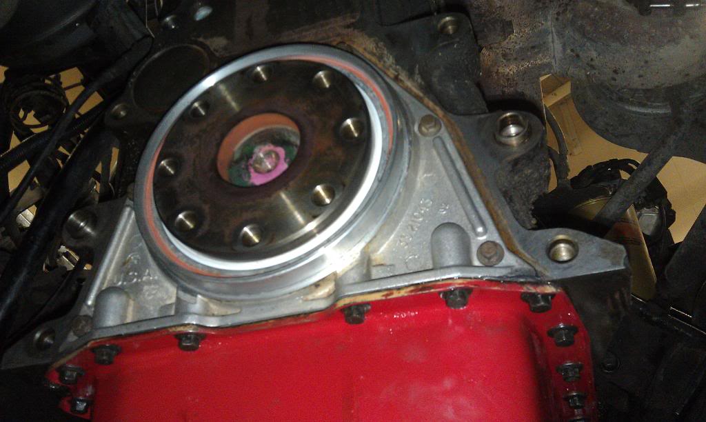
Here's the rear end of the crankshaft, this surface around the circumfrence should be cleaned thoroughly with brake cleaner and a rag to make sure that it has no residue of the old seal left (which mine had). It should be PERFECTLY smooth before you replace the seal.
This is the tool that the seal came with:
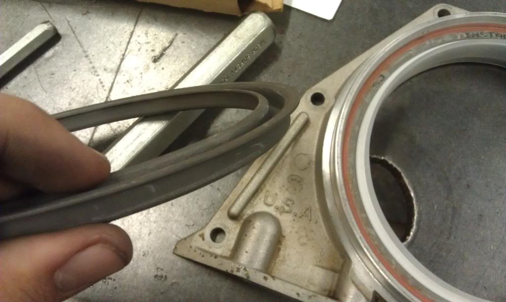
You get the seal started into the (cleaned) housing and tap the tool to press the seal into its spot and make sure that it sits perfectly square to the housing.
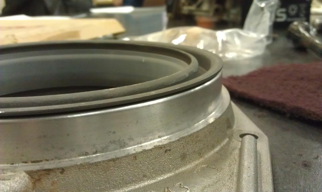
Stick the gasket on the perfectly cleaned surface of the other side of the housing, line up the holes, and (at least I had to) trim the excess gasket off of the bottom on both sides.
And with the use of a plastic ring included in the kit to stretch the seal around the crankshaft, push the seal housing on to the rear of the motor. At this point I would definitely recommend torquing the horizontal 6 bolts to the (i believe but don't quote me on this) 7-8 ft/lbs before you torque the vertical bolts through the oilpan so that the oilpan bolts don't pull the seal housing down and put uneven pressure on the seal around the crankshaft. I also applied a small amount of silicon sealant at the bottom of the gasket in both corners to seal between the oilpan gasket and the crankshaft seal housing gasket.
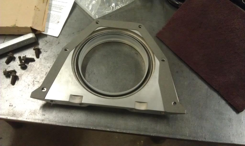
At this point I would recommend torquing the starter onto the new block adapter plate to the 32 ft/lbs and then place the plate on the rear of the motor. Its your call but the starter bolts were a tad of a pain in my opinion and it was easier this way.
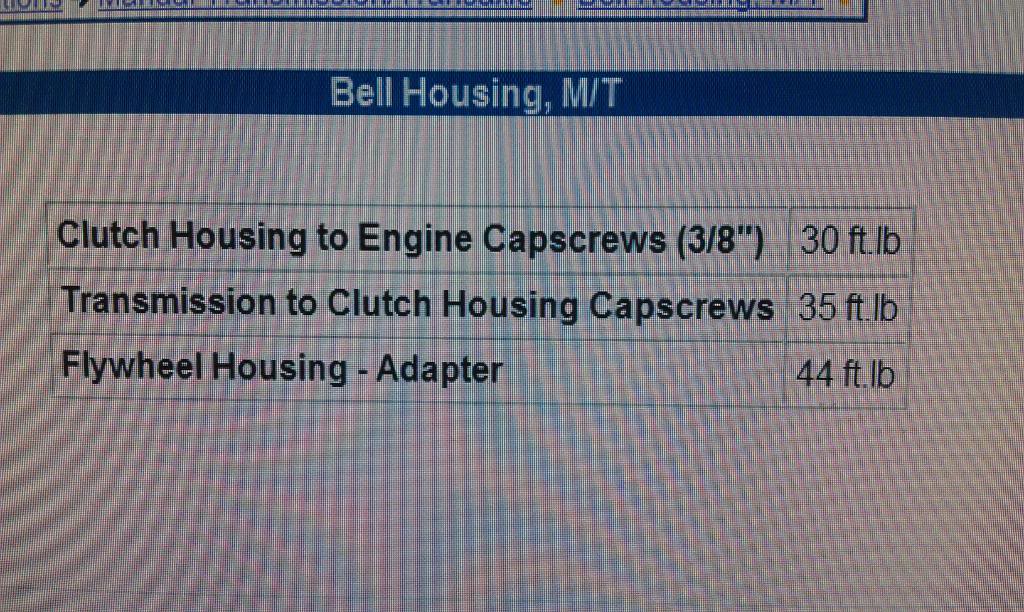
Here are the specs for the next couple torques you'll need:
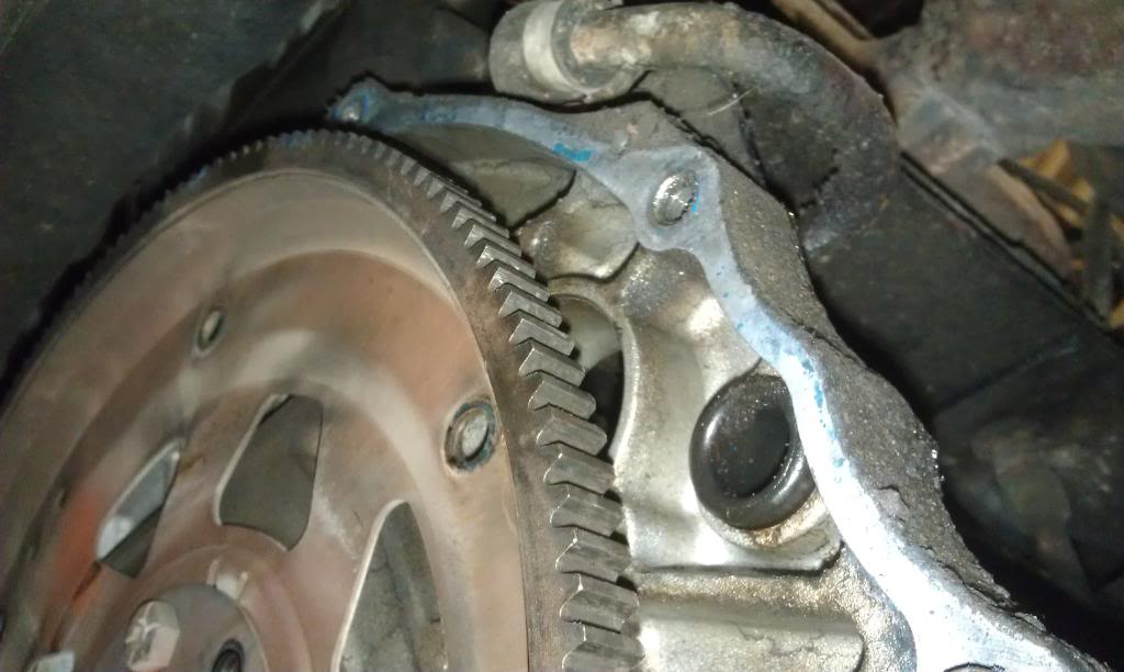
The flywheel bolts all asked for loc-tite on them, and after mounting the clutch disk and pressure plate you have:
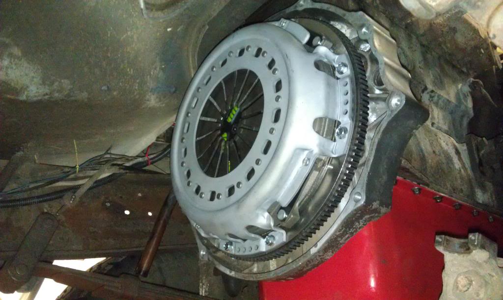
The clutch I installed was a 13" (stock is 12.25") flywheel and clutch combo from DieselAutoPower that they recommended when I requested a price quote. The one I went with was a Valair kit that I got for just over $600 shipped that's rated to 450hp and 900ft/lbs I believe.
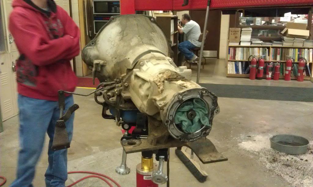
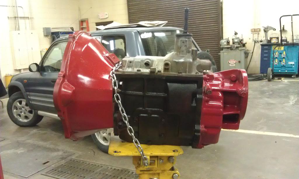
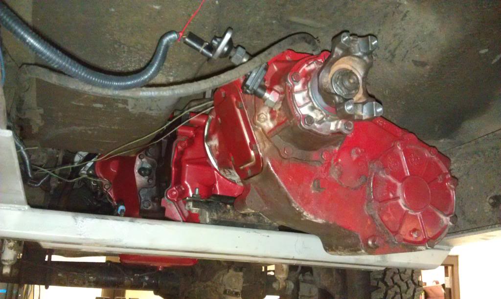
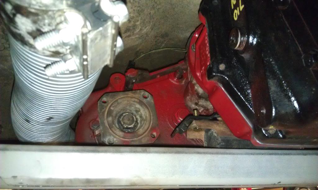
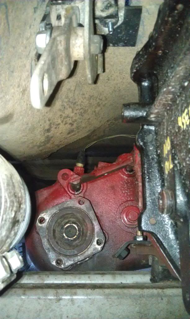
My new tranny ready to go in, by the way I painted all of this with red high-temp engine enamel because I like light colors on the underside of a vehicle so you can easier diagnose leaks and other issues in the future. It also make it much more impressive looking when showing off to fellow bombers!
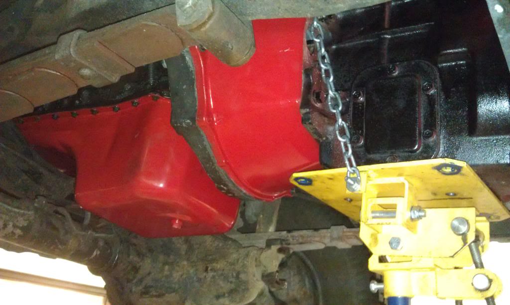
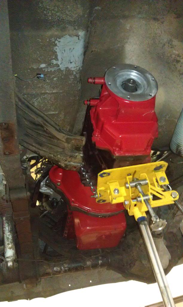
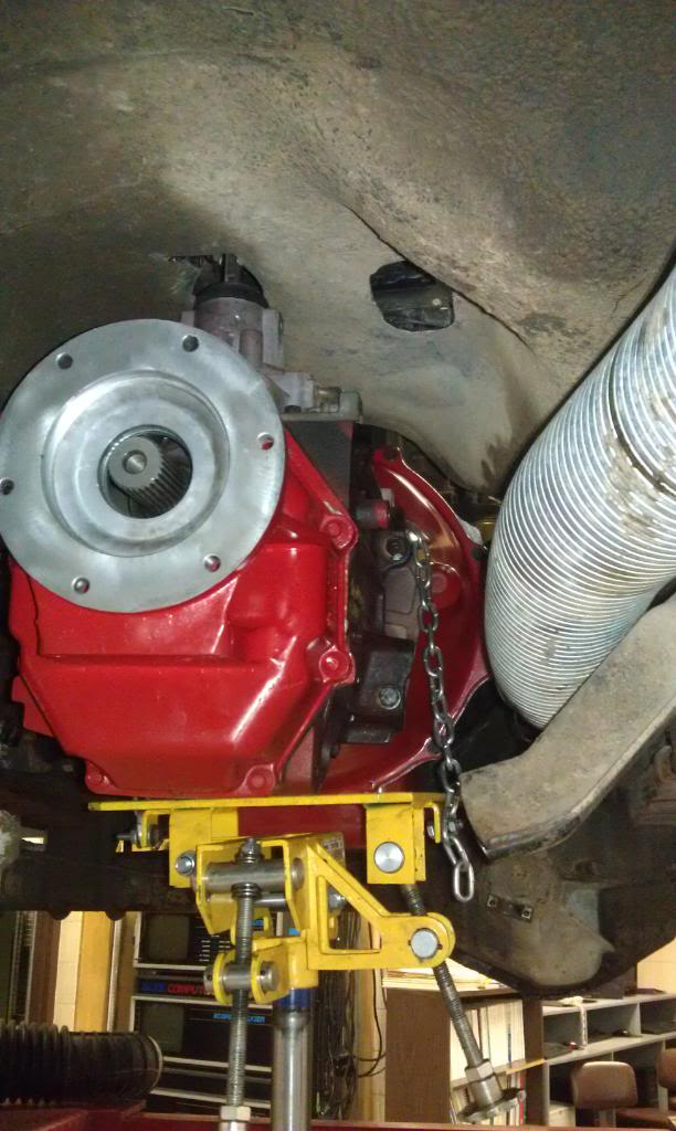
And it's in!
These other two wires are much longer and run to the transfercase for the speedo sender and the 4WD indicator. These I wrapped in corregated tubing and left otherwise alone.
The next two pics are of the oil-pan gasket change. My gasket appeared to be leaking so I decided to replace it when I had the truck apart anyway, and it turns out that you have to lift the motor a couple inches to clear the crossmember with the pan. The two bottom-most bolts on the motor mounts (the mostly vertical ones with the 19mm nuts) fit in oblong holes which make the motor easiest to sit back down in the right place. When sitting the motor back down, in my case the passenger side had to be at the top of the hole and the driver side down for the motor to sit level and for the starter to clear the framerail because the starter from the 2nd gen has a different orientation.
And my shiny repainted oilpan:
The next couple pics are of the rear main seal replacement that I decided to do because it was cheap and now would be the time to do it. This is the seal and gasket kit I bought. :
Here's the rear end of the crankshaft, this surface around the circumfrence should be cleaned thoroughly with brake cleaner and a rag to make sure that it has no residue of the old seal left (which mine had). It should be PERFECTLY smooth before you replace the seal.
This is the tool that the seal came with:
You get the seal started into the (cleaned) housing and tap the tool to press the seal into its spot and make sure that it sits perfectly square to the housing.
Stick the gasket on the perfectly cleaned surface of the other side of the housing, line up the holes, and (at least I had to) trim the excess gasket off of the bottom on both sides.
And with the use of a plastic ring included in the kit to stretch the seal around the crankshaft, push the seal housing on to the rear of the motor. At this point I would definitely recommend torquing the horizontal 6 bolts to the (i believe but don't quote me on this) 7-8 ft/lbs before you torque the vertical bolts through the oilpan so that the oilpan bolts don't pull the seal housing down and put uneven pressure on the seal around the crankshaft. I also applied a small amount of silicon sealant at the bottom of the gasket in both corners to seal between the oilpan gasket and the crankshaft seal housing gasket.
At this point I would recommend torquing the starter onto the new block adapter plate to the 32 ft/lbs and then place the plate on the rear of the motor. Its your call but the starter bolts were a tad of a pain in my opinion and it was easier this way.
Here are the specs for the next couple torques you'll need:
The flywheel bolts all asked for loc-tite on them, and after mounting the clutch disk and pressure plate you have:
The clutch I installed was a 13" (stock is 12.25") flywheel and clutch combo from DieselAutoPower that they recommended when I requested a price quote. The one I went with was a Valair kit that I got for just over $600 shipped that's rated to 450hp and 900ft/lbs I believe.
My new tranny ready to go in, by the way I painted all of this with red high-temp engine enamel because I like light colors on the underside of a vehicle so you can easier diagnose leaks and other issues in the future. It also make it much more impressive looking when showing off to fellow bombers!
And it's in!
Here you'll notice a small lip in the rear end of the NV4500 tailhousing. This lip is actually too small for the adapter from SHS diesel if that's the way you go.
What I did was remove the tailhousing and remove the lip and a tiny bit of extra aluminum with a carbide bit on an air die grinder so the adapter will fit.
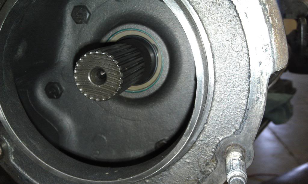
And this is the only picture I have of the input seal replacement of the transfercase, but you get the Idea. The seal is pressed into the "Racetrack 8" to circular 6 bolt adapter housing, and was easily tapped out and the new ones pressed in when I removed the housing.
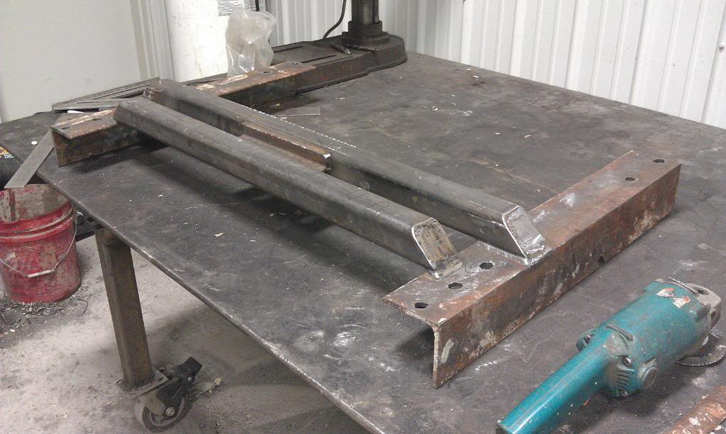
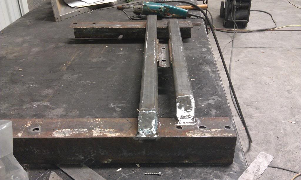
So at this point Im kind of changing gears here (nice play on words right? haha) and doing a bit of fabrication. I forgot to mention earlier that the transmission crossmember will no longer work for a couple of reasons. One of those reasons being that the Auto tranny used two bit rubber washers as mount bushings and the NV4500 uses a single piece rubber bar. This is something I had thought about before I started the project but realistically had no clue what I was going to have to do but wasn't too worried about it because i'm a welder and that would be the least of my worries. What I ended up using was 2 pieces of 3x3x1/4 angle iron to run the length of the straight section of frame in that area, and some 2x2x1/4 square tube as crossmember pieces with a piece of 1x2 C-channel welded between the 2x2 that the transmission mounts to.
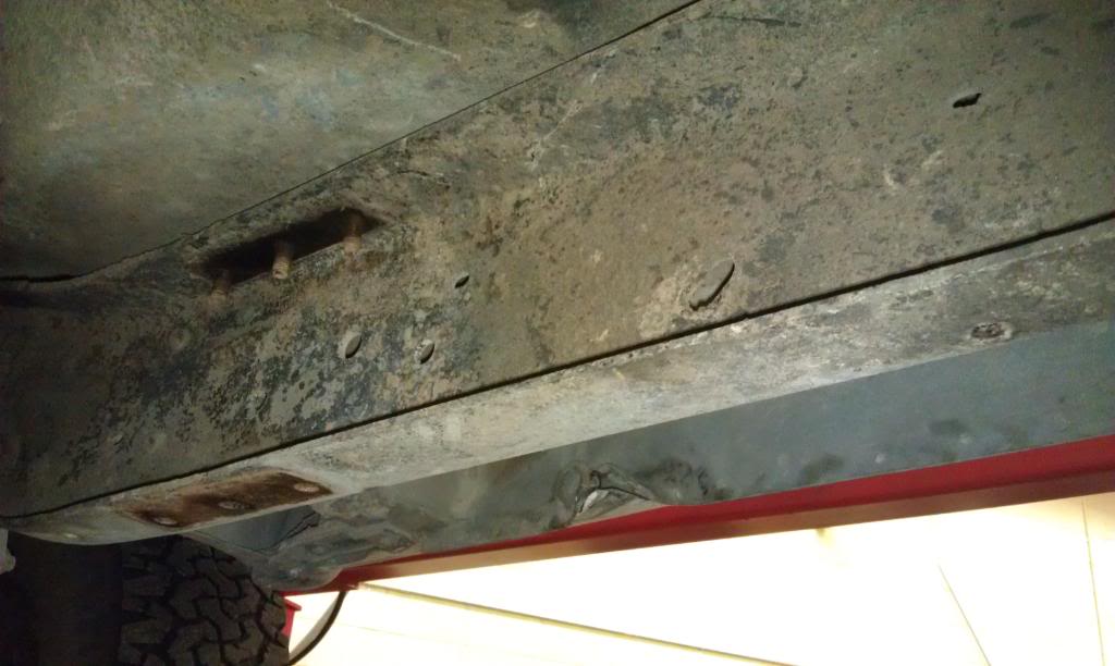
So here's the frame we're working with, notice the 3 holes on the bottom of the C up front that the old crossmember bolted to. and also the two holes much farther rearward on either side that the transfercase skid bolted to and the one oblong hole on either side on the vertical part of the frame. All of these holes are utilized with my crossmember.
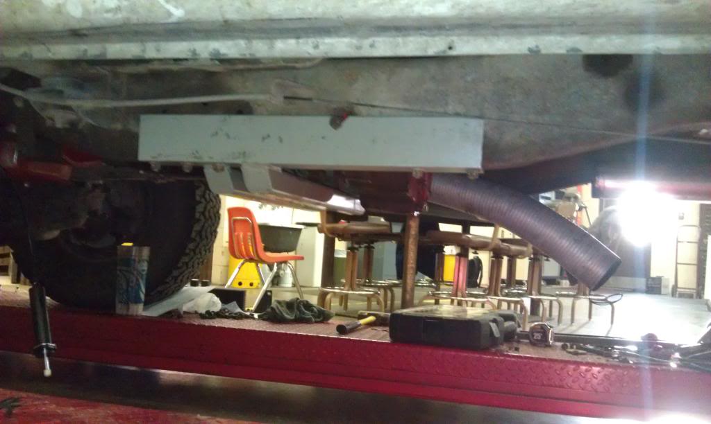
And here's what I ended up with!
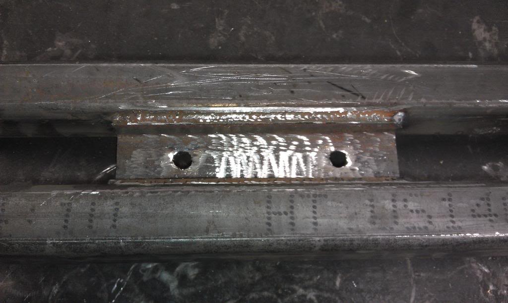
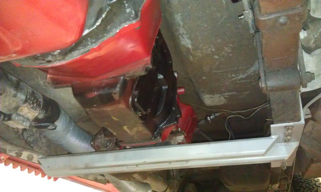
And here's with it all mounted up (and painted) and the transfercase put back in. The transfercase's paint job looks like crap because I ran out of paint halfway through and really just didn't care because by the looks of the internals of my transfercase, I would most likely be pulling it back out in the upcoming year or so.
I almost freaked out when I saw this:
and thought that my front driveshaft wasn't going to fit, but I put the shaft up and saw that it has tons of clearance. But its something to keep in mind when you go to build a crossmember of your own.

I also plan on adding some supports that go up to those upper 3 holes on either side of the frame like the stock crossmember did but at the moment im gonna just get it working.
What I did was remove the tailhousing and remove the lip and a tiny bit of extra aluminum with a carbide bit on an air die grinder so the adapter will fit.
And this is the only picture I have of the input seal replacement of the transfercase, but you get the Idea. The seal is pressed into the "Racetrack 8" to circular 6 bolt adapter housing, and was easily tapped out and the new ones pressed in when I removed the housing.
So at this point Im kind of changing gears here (nice play on words right? haha) and doing a bit of fabrication. I forgot to mention earlier that the transmission crossmember will no longer work for a couple of reasons. One of those reasons being that the Auto tranny used two bit rubber washers as mount bushings and the NV4500 uses a single piece rubber bar. This is something I had thought about before I started the project but realistically had no clue what I was going to have to do but wasn't too worried about it because i'm a welder and that would be the least of my worries. What I ended up using was 2 pieces of 3x3x1/4 angle iron to run the length of the straight section of frame in that area, and some 2x2x1/4 square tube as crossmember pieces with a piece of 1x2 C-channel welded between the 2x2 that the transmission mounts to.
So here's the frame we're working with, notice the 3 holes on the bottom of the C up front that the old crossmember bolted to. and also the two holes much farther rearward on either side that the transfercase skid bolted to and the one oblong hole on either side on the vertical part of the frame. All of these holes are utilized with my crossmember.
And here's what I ended up with!
And here's with it all mounted up (and painted) and the transfercase put back in. The transfercase's paint job looks like crap because I ran out of paint halfway through and really just didn't care because by the looks of the internals of my transfercase, I would most likely be pulling it back out in the upcoming year or so.
I almost freaked out when I saw this:
and thought that my front driveshaft wasn't going to fit, but I put the shaft up and saw that it has tons of clearance. But its something to keep in mind when you go to build a crossmember of your own.
I also plan on adding some supports that go up to those upper 3 holes on either side of the frame like the stock crossmember did but at the moment im gonna just get it working.

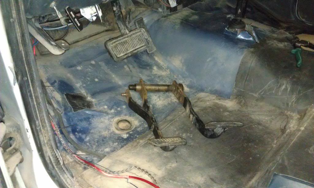
The pedal setup includes the master cylinder that bolts via 4 bolts to the inside of the firewall above the clutch pedal, and the clutch pedal and new (smaller) brake pedal that both pivot on the same rod. This is what the parts i got look like:
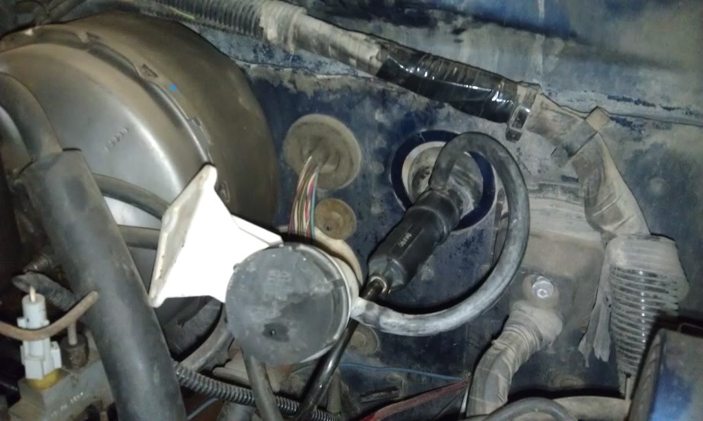
And this is the master Cylinder poking through the firewall and the reservoir that will screw into the firewall directly above it. There are 3 dents on the firewall where the holes need to be and I just used self drilling screws.
The brake and clutch pedal pivot on a rod that slips through a few baffle like plates that are spot welded to the firewall. My pedals (which came from Holst Truck Parts) came with the two pedals, the rod, and the little plastic bushings that fit between them. You have to pull a little screw that holds the plate on the end of the rod to the first baffle it passes through, slide the rod out (which proved easier said than done in that tight space and it fit rather tightly), and hold the two new pedals in place while you slip the new (at least cleaned and greased) rod back through and replace the screw that holds it all in.

Diesel Fan
Joined: Jun 2010
Posts: 55
Likes: 4
From: Charles Town, WV
Good thread, I've got a 4500 sitting in the garage I've been meaning to swap in. I should have most of the parts to do it now, just need to get unlazy and do it haha
I picked up the Advance Adapters bellhousing kit to do my swap with as I couldn't get my hands on the 2nd gen dodge parts for less than that kit.
I picked up the Advance Adapters bellhousing kit to do my swap with as I couldn't get my hands on the 2nd gen dodge parts for less than that kit.


Here's about the bast picture I can get of the rod that holds the pedals in:
And here's where the master cylinder bolts in, the part of the master cylinder that bolts to the truck is the part with the yellow lettering on it.
And a pic with the reservoir actually mounted:
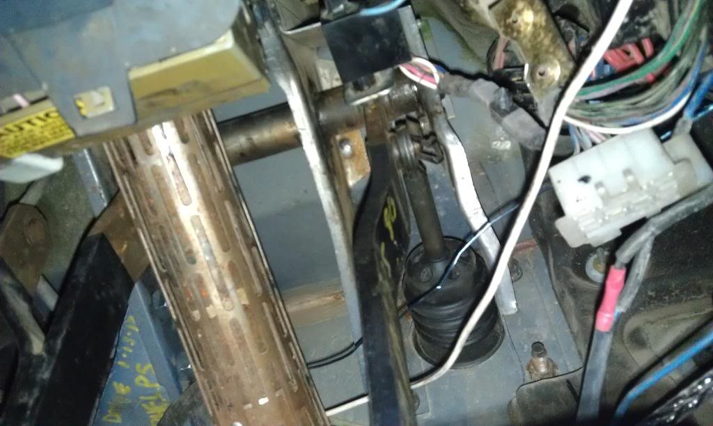
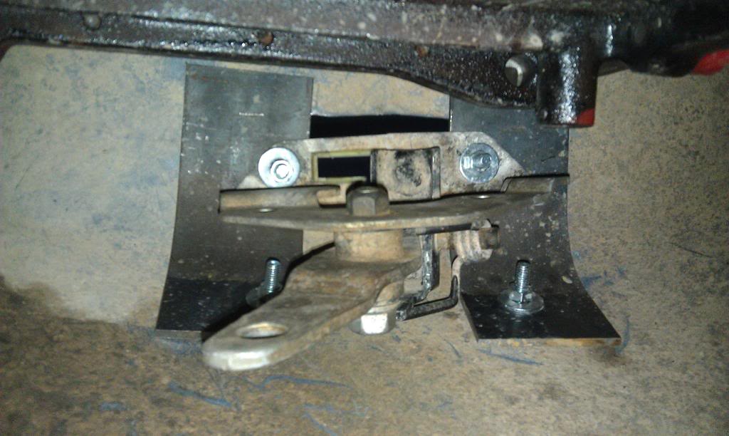
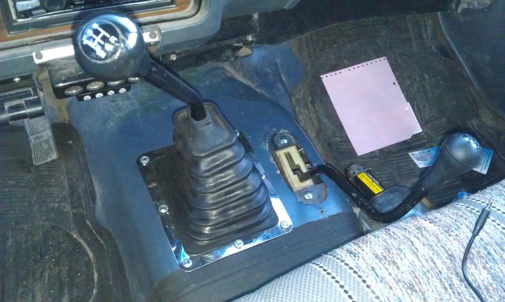
And as far as the transfercase linkage goes, I ended up using the one from the 97 dodge that came with the tranny , and basically just used it backwards (because the 2nd gen transfercase is left side front shaft). I made these brakcets to mount the shifter to the floor out of some 3x1/4" flat strap and used carriage bolts so I wouldn't have big bolt heads under the rubber floor mat ill be installing.
And a pic down the line that the front driveshaft occupies:
The shifter arm will actually need to be cut down and a hole drilled closer to the pivot point for the shifter to have the same throw as the old shifter. I really only used the new shifter because my old one was messed up and I liked the newer style one more anyway. Ill be able to use the old linkage after I cut 4" out of the center and weld it back together.
And I still need to find a nice matching rectangular boot for the 4WD shifter but here's the finished product for the inside!
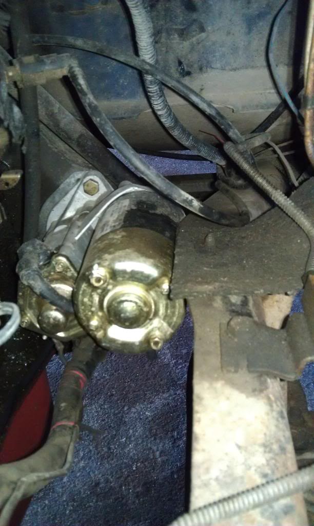
Also, as I mentioned earlier, the starter has a different orientation the the old first gen one did, here's how close it sits to the frame, but i can slide the tip of my finger between it and the framerail so I guess that's enough space.
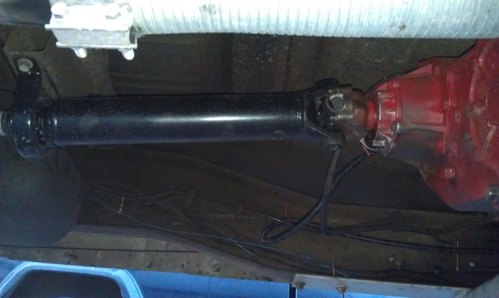
This is the new front half of the rear driveshaft that will have to be lengthened. In my case it was 19" exactly from the center of the carrier bearing mounting holes to the surface of the yoke on the transfercase that the U-joint straps bolt to. The old shaft was 15", and I also replaced the carrier bearing.
---AutoMerged DoublePost---
Thanks! Yeah, with the old tranny and its crossmember I had to use flex tube to get it to bend around right and when I actually get it all together and tighten down the clamps I can tell there are no leaks so I guess it's working...
And thanks agian, I hope the crossmember looks alright because my living depends on my fabrication skills haha! I kinda figured that strength was the most improtant thing on this one and weight didn't really matter so what the heck?!? It is definitely much heavier than the old one because of the steel's thickness but who cares on a truck like this? I would still like to make supports that run to the top of the frame like the old one did to make sure to prevent twisting forces on the frame from having any effect, and I think the Angle Iron sides will help with the framerails staying in equal forward to back positions as well as vertical support.
---AutoMerged DoublePost---
Oh, and one more thing I forgot to mention that took me a while to get right; the clutch slave cylinder on these has no bleeding screw or anything like that, and what you have to do is press the slave cylinder in all the way with your hands and as you slowly release the rod (allow it to extend) pour brake fluid into the cylinder. once its past the point that the plastic strings would hold it at, press it back in just far enough to connect the strings. at this point you have to fill the reservoir and as you make sure there is no air in the lines by pressing the clutch pedal, when you're getting pure fluid, slip the hose into the filled slave cylinder and slip in the pin. Then you mount the slave on the transmission and the first time you depress the clutch pedal it breaks the strings and pushes into the clutch fork. The only piece of instruction I was able to find on this whole thing is to press the clutch down repeatedly (like 10 to 20 times I think it said) and do it quickly. I don't know why but Ive got just under 1000 miles on it so far, so I guess it worked.
And here's where the master cylinder bolts in, the part of the master cylinder that bolts to the truck is the part with the yellow lettering on it.
And a pic with the reservoir actually mounted:
And as far as the transfercase linkage goes, I ended up using the one from the 97 dodge that came with the tranny , and basically just used it backwards (because the 2nd gen transfercase is left side front shaft). I made these brakcets to mount the shifter to the floor out of some 3x1/4" flat strap and used carriage bolts so I wouldn't have big bolt heads under the rubber floor mat ill be installing.
And a pic down the line that the front driveshaft occupies:
The shifter arm will actually need to be cut down and a hole drilled closer to the pivot point for the shifter to have the same throw as the old shifter. I really only used the new shifter because my old one was messed up and I liked the newer style one more anyway. Ill be able to use the old linkage after I cut 4" out of the center and weld it back together.
And I still need to find a nice matching rectangular boot for the 4WD shifter but here's the finished product for the inside!
Also, as I mentioned earlier, the starter has a different orientation the the old first gen one did, here's how close it sits to the frame, but i can slide the tip of my finger between it and the framerail so I guess that's enough space.
This is the new front half of the rear driveshaft that will have to be lengthened. In my case it was 19" exactly from the center of the carrier bearing mounting holes to the surface of the yoke on the transfercase that the U-joint straps bolt to. The old shaft was 15", and I also replaced the carrier bearing.
---AutoMerged DoublePost---
And thanks agian, I hope the crossmember looks alright because my living depends on my fabrication skills haha! I kinda figured that strength was the most improtant thing on this one and weight didn't really matter so what the heck?!? It is definitely much heavier than the old one because of the steel's thickness but who cares on a truck like this? I would still like to make supports that run to the top of the frame like the old one did to make sure to prevent twisting forces on the frame from having any effect, and I think the Angle Iron sides will help with the framerails staying in equal forward to back positions as well as vertical support.
---AutoMerged DoublePost---
Oh, and one more thing I forgot to mention that took me a while to get right; the clutch slave cylinder on these has no bleeding screw or anything like that, and what you have to do is press the slave cylinder in all the way with your hands and as you slowly release the rod (allow it to extend) pour brake fluid into the cylinder. once its past the point that the plastic strings would hold it at, press it back in just far enough to connect the strings. at this point you have to fill the reservoir and as you make sure there is no air in the lines by pressing the clutch pedal, when you're getting pure fluid, slip the hose into the filled slave cylinder and slip in the pin. Then you mount the slave on the transmission and the first time you depress the clutch pedal it breaks the strings and pushes into the clutch fork. The only piece of instruction I was able to find on this whole thing is to press the clutch down repeatedly (like 10 to 20 times I think it said) and do it quickly.
I don't know why but Ive got just under 1000 miles on it so far, so I guess it worked.
Last edited by That93Guy; Feb 24, 2012 at 10:21 PM. Reason: Automerged Doublepost


