
3rd Gen Tech: Isspro EV2 Gauge Install

Thread Starter
|
Newbie
Joined: Apr 2009
Posts: 8
Likes: 0
From: Phoenix, AZ
Gauge Power/Illumination
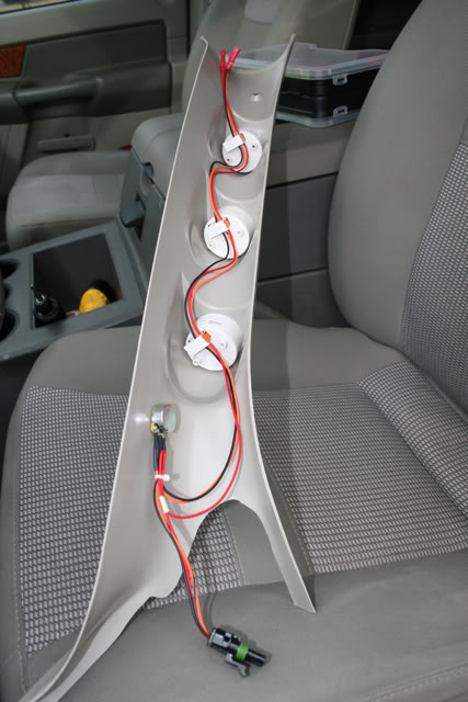
My first task was getting the gauge pillar wired up and ready to go. I decided to use Weather Pack connectors for all connections to the pillar. This will make it easy to move/remove if need be. I�m still waiting on parts to actually hook up the senders, so for the time being I�m just concentrating on getting the power and illumination circuits installed.
One of the things I like about the ISSPRO EV2 gauge�s is that the power/illumination/ground can be installed in serial, or a daisy chain fashion.
Starting at the bottom we have the Weather Pack with the power/illumination/ground coming into the gauge pillar. It then goes through the ISSPRO lighting harness and finally to the gauges. I left myself enough room on the top so that if I ever install gauges above the rear-view mirror I can just crimp on another Weather Pack connector and be ready to go.
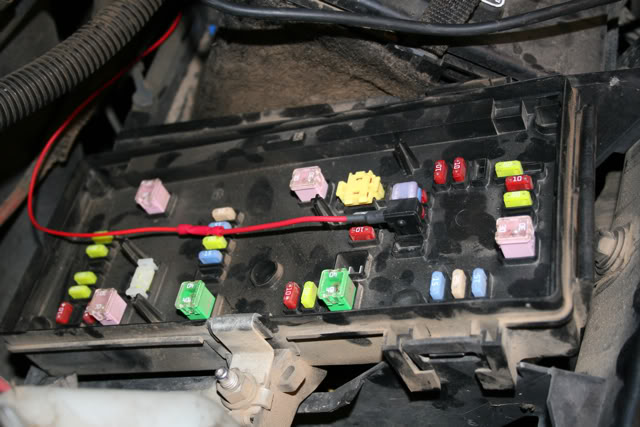
For switched power I used an Add-A-Circuit in the fusebox. I used fuse #30 which was labeled as a spare, but it turns out that it actually isn't a spare. I accidentally forgot to plug it back in and when I started up the truck I got an ABS and E-Brake light on the dash. I took the easy way out and just notched the fuse block and cover. Probably should have drilled a hole and used a grommet, but I don't expect to have any problems.
I don't have a picture of where I mounted the ground but I just reused an existing ground under the dash.
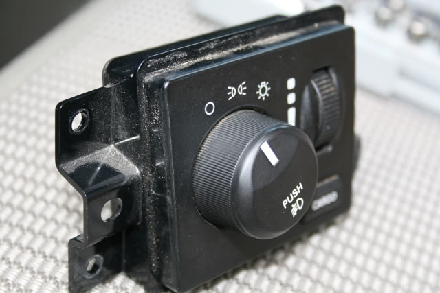
The illumination circuit needs to be tapped into the dimmer wire at the headlight switch. Gaining access to the switch was fairly easy. I just pulled away the plastic dash piece far enough to get a right angle screwdriver behind the headlight switch. Remove three screws and the headlight switch pulls out of the dash. On some trucks the headlight switch will pop out without removing any screws, but mine would not. You definitely want to verify before you go prying on your dash.
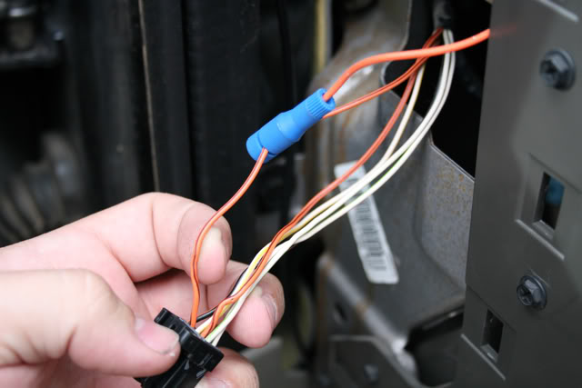
On my 2006 this wire is one of the two orange with brown stripe wires. You're supposed to probe the wire to find the one that dims with the gauge cluster. Somehow I managed to probe the same wire twice which led me to believe that neither of them worked. I went back the next day and found the correct wire, as pictured here.
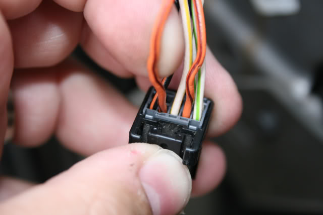
Tapped it with a Posi-Tap and we were good to go.
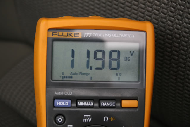
Dimmer all the way up...
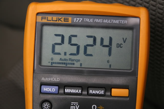
Dimmer all the way down...
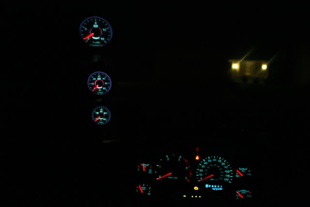
Final product. Gauges have power and illumination but no sender connections yet. The gauges will dim with the factory gauges and I can also fine tune the brightness with Isspro lighting harness to get a perfect brightness match.
---AutoMerged DoublePost---
Pyrometer
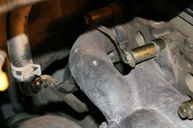
This was the part that I was most worried about but it ended up being super easy. The general consensus is that in order to get a "worst case" reading, it is best to install the thermocouple in between cylinders 5 and 6. This is considered to be the hottest location and thus will give you the earliest indicator of an EGT problem.
Drilling the manifold was very straight forward. I was unable to find the required "R" drill bit locally so I ordered the bit and tap from Diesel Manor along with my transmission line. If you decide to install the thermocouple in between 5 and 6 like I did, you will definitely need a right angle drill or a right angle adapter for your drill. I used an 18V Right Angle DeWalt and it worked perfectly. I started with a very small bit and worked my way up slowly to the "R" bit. I used light pressure on the drill and had a shop vac placed over the hole to vacuum up all the shavings. Once I was finished drilling I used a pen magnet to pick up all the shavings that dropped down into the manifold. I was very surprised by how little there actually were.
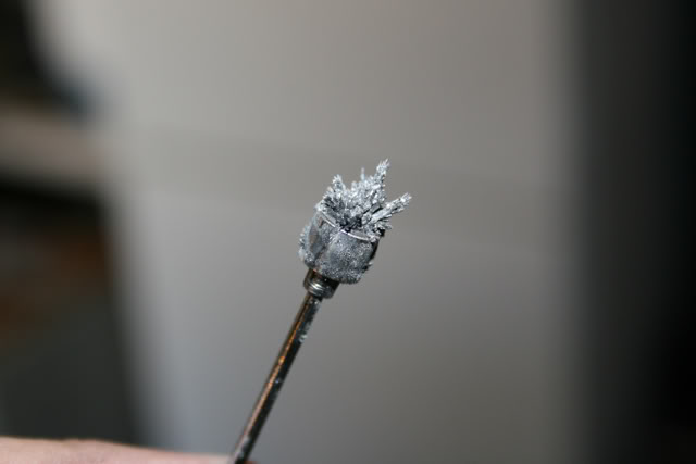
Tapping the manifold was a different story. In hindsight I should have greased the tap as a lot of shavings made it into the manifold. It took numerous passes to get the magnet coming out clean.
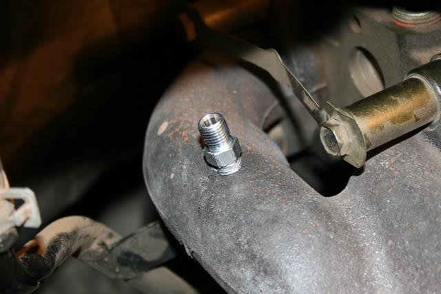
Now it's time to install the probe insert. Apply anti-seize to the threads and screw in the insert.
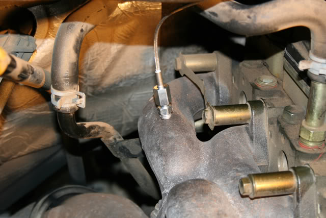
Install the probe into the insert doing your best to place the tip in the middle of the exhaust stream. Tighten the nut and you're done.
My first task was getting the gauge pillar wired up and ready to go. I decided to use Weather Pack connectors for all connections to the pillar. This will make it easy to move/remove if need be. I�m still waiting on parts to actually hook up the senders, so for the time being I�m just concentrating on getting the power and illumination circuits installed.
One of the things I like about the ISSPRO EV2 gauge�s is that the power/illumination/ground can be installed in serial, or a daisy chain fashion.
Starting at the bottom we have the Weather Pack with the power/illumination/ground coming into the gauge pillar. It then goes through the ISSPRO lighting harness and finally to the gauges. I left myself enough room on the top so that if I ever install gauges above the rear-view mirror I can just crimp on another Weather Pack connector and be ready to go.
For switched power I used an Add-A-Circuit in the fusebox. I used fuse #30 which was labeled as a spare, but it turns out that it actually isn't a spare. I accidentally forgot to plug it back in and when I started up the truck I got an ABS and E-Brake light on the dash. I took the easy way out and just notched the fuse block and cover. Probably should have drilled a hole and used a grommet, but I don't expect to have any problems.
I don't have a picture of where I mounted the ground but I just reused an existing ground under the dash.
The illumination circuit needs to be tapped into the dimmer wire at the headlight switch. Gaining access to the switch was fairly easy. I just pulled away the plastic dash piece far enough to get a right angle screwdriver behind the headlight switch. Remove three screws and the headlight switch pulls out of the dash. On some trucks the headlight switch will pop out without removing any screws, but mine would not. You definitely want to verify before you go prying on your dash.
On my 2006 this wire is one of the two orange with brown stripe wires. You're supposed to probe the wire to find the one that dims with the gauge cluster. Somehow I managed to probe the same wire twice which led me to believe that neither of them worked. I went back the next day and found the correct wire, as pictured here.
Tapped it with a Posi-Tap and we were good to go.
Dimmer all the way up...
Dimmer all the way down...
Final product. Gauges have power and illumination but no sender connections yet. The gauges will dim with the factory gauges and I can also fine tune the brightness with Isspro lighting harness to get a perfect brightness match.
---AutoMerged DoublePost---
Pyrometer
This was the part that I was most worried about but it ended up being super easy. The general consensus is that in order to get a "worst case" reading, it is best to install the thermocouple in between cylinders 5 and 6. This is considered to be the hottest location and thus will give you the earliest indicator of an EGT problem.
Drilling the manifold was very straight forward. I was unable to find the required "R" drill bit locally so I ordered the bit and tap from Diesel Manor along with my transmission line. If you decide to install the thermocouple in between 5 and 6 like I did, you will definitely need a right angle drill or a right angle adapter for your drill. I used an 18V Right Angle DeWalt and it worked perfectly. I started with a very small bit and worked my way up slowly to the "R" bit. I used light pressure on the drill and had a shop vac placed over the hole to vacuum up all the shavings. Once I was finished drilling I used a pen magnet to pick up all the shavings that dropped down into the manifold. I was very surprised by how little there actually were.
Tapping the manifold was a different story. In hindsight I should have greased the tap as a lot of shavings made it into the manifold. It took numerous passes to get the magnet coming out clean.
Now it's time to install the probe insert. Apply anti-seize to the threads and screw in the insert.
Install the probe into the insert doing your best to place the tip in the middle of the exhaust stream. Tighten the nut and you're done.
Last edited by 65StangBoy; Nov 27, 2009 at 01:10 PM. Reason: Automerged Doublepost

Thread
Thread Starter
Forum
Replies
Last Post
CHAMP31707
For Sale
0
Jun 1, 2015 04:03 PM
CGwill
24 Valve 2nd Gen Dodge Cummins 98.5-02
0
Jan 26, 2015 02:10 AM


