
how do you test the glowplug relay


To test the GP relay, you can use a test light. Just find a good ground and test the switched side as someone cycles the ignition. If it goes on and off again ok.
To test the glow plugs, you can use an Ohmmeter to check the resistance between the terminals. Anything 5 or less is ok, if you get no reading then it's toast.
Also make sure the buss bar (if you have Federal emissions LB7) is not corroded or rusty as this could effect operation.
To test the glow plugs, you can use an Ohmmeter to check the resistance between the terminals. Anything 5 or less is ok, if you get no reading then it's toast.
Also make sure the buss bar (if you have Federal emissions LB7) is not corroded or rusty as this could effect operation.
Thread Starter
|
Diesel Fan
Joined: Apr 2009
Posts: 72
Likes: 1
From: Medford Wisconsin
Ok from what I gather the glowplug relay is behind the driverside valve cover in the black little box with two connectors pluged into it is that it? do I unplug the connectors and take the box out or am I looking at the wrong part here? Thanks
Super Moderator
Joined: Oct 2007
Posts: 14,872
Likes: 764
From: Houston, Tx

is it a federal or cali emmisons truck, if its a cali it will most likely be the glow plugs. if its a fedral it will most likely be the controller.
The Federal has the glow plugs connected together with the black bar going across all 4 on each side.
let us know so i can post more info
The Federal has the glow plugs connected together with the black bar going across all 4 on each side.
let us know so i can post more info
Thread Starter
|
Diesel Fan
Joined: Apr 2009
Posts: 72
Likes: 1
From: Medford Wisconsin
I don't have any power on my bar. It must be federal, it has the solid black bar across the gp. how do it get the relay out of there. Do I just unplug the two connectors or is there some more wires to unplug on her. Thanks for all the help Guys. Later 
Super Moderator
Joined: Oct 2007
Posts: 14,872
Likes: 764
From: Houston, Tx
There i two wires you need to unbolt, one that goes to the intake air heater an the 12v supply to the relay. the rest the two pink wires and 4 wire connector can be undone at the connectors.
there is two 13mm nuts holding down the relay IIRC and they easily accessable. it also helps to undo the wire going down to the glow plug from the relay before unbolting it.
there is two 13mm nuts holding down the relay IIRC and they easily accessable. it also helps to undo the wire going down to the glow plug from the relay before unbolting it.
Super Moderator
Joined: Oct 2007
Posts: 14,872
Likes: 764
From: Houston, Tx
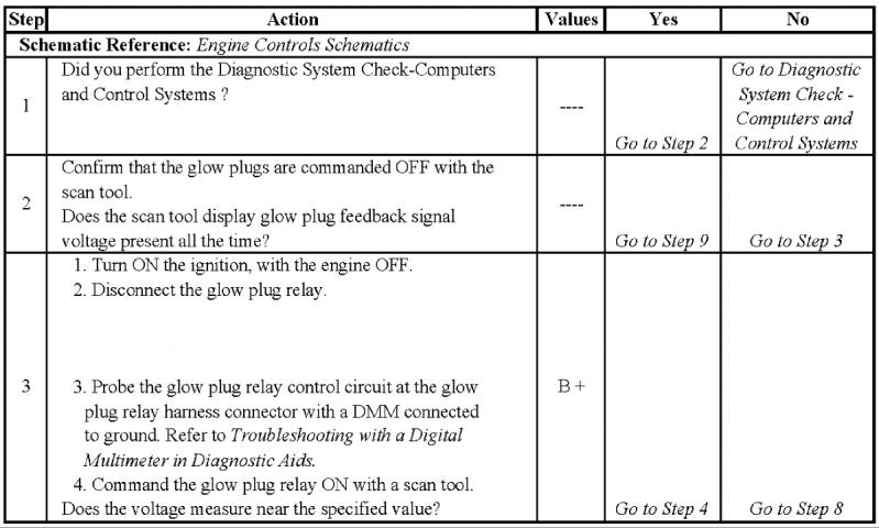
CIRCUIT DESCRIPTION
The glow plug system is used to assist in providing the heat required to begin combustion during cold engine temperatures. The glow plugs are heated before and during cranking, as well as initial engine operation. The engine control module (ECM) controls the glow plug ON times by monitoring coolant temperature and glow plug voltage.
CONDITIONS FOR RUNNING THE DTC
The ignition switch in the ON position.
CONDITIONS FOR SETTING THE DTC
If the glow plug relay is stuck in the ON position, check for proper operation of the glow plugs, refer to Glow Plug System Diagnosis. When glow plugs are commanded ON by the scan tool, an internal ECM timer protects the glow plugs from damage by cycling them ON for 3 seconds and then OFF for 12 seconds . See: Component Tests and General Diagnostics\Glow Plug System Diagnosis
The glow plug output feed wire nut and battery feed wire nut at the relay should be checked for proper torque, 5 N.m (44 lb in) and for corrosion.
An intermittent may be caused by the following:
The glow plug system is used to assist in providing the heat required to begin combustion during cold engine temperatures. The glow plugs are heated before and during cranking, as well as initial engine operation. The engine control module (ECM) controls the glow plug ON times by monitoring coolant temperature and glow plug voltage.
CONDITIONS FOR RUNNING THE DTC
The ignition switch in the ON position.
CONDITIONS FOR SETTING THE DTC
- The ECM has commanded glow plugs ON and the glow plug signal voltage is less than 4 volts .
- The ECM has commanded glow plugs OFF and the glow plug signal voltage is more than 4 volts .
- The control module illuminates the malfunction indicator lamp (MIL) on the second consecutive ignition cycle that the diagnostic runs and fails.
- The control module records the operating conditions at the time the diagnostic fails. The first time the diagnostic fails, the control module stores this information in the Failure Records. If the diagnostic reports a failure on the second consecutive ignition cycle, the control module records the operating conditions at the time of the failure. The control module writes the operating conditions to the Freeze Frame and updates the Failure Records.
- The control module turns OFF the malfunction indicator lamp (MIL) after 3 consecutive ignition cycles that the diagnostic runs and does not fail.
- A current DTC, Last Test Failed, clears when the diagnostic runs and passes.
- A history DTC clears after 40 consecutive warm-up cycles, if no failures are reported by this or any other emission related diagnostic.
- Clear the MIL and the DTC with a scan tool.
If the glow plug relay is stuck in the ON position, check for proper operation of the glow plugs, refer to Glow Plug System Diagnosis. When glow plugs are commanded ON by the scan tool, an internal ECM timer protects the glow plugs from damage by cycling them ON for 3 seconds and then OFF for 12 seconds . See: Component Tests and General Diagnostics\Glow Plug System Diagnosis
The glow plug output feed wire nut and battery feed wire nut at the relay should be checked for proper torque, 5 N.m (44 lb in) and for corrosion.
An intermittent may be caused by the following:
- Poor connections
- Rubbed through wire insulation
- Broken wire inside the insulation


