05 Duramax smokes and won't move
#11
 12-04-2009, 03:38 PM

Diesel Wrench

#12
12-04-2009, 04:35 PM

That is one of the problems in that inorder for the check engine light to trip the code has to show up two ignition cycles in a row. When this thing happens the truck will not move and with the pedal to the floor puts out nothing but black smoke. The other day it could not move a 4k lb trailer, stood still and smoked. Just put in another new air filter just to take that out of the equation. The MAF is clean but will clean again this weekend. Also it will set a code with out me pulling anything. Thanks for the info.
#13
12-04-2009, 04:42 PM

Verify the integrity of the air induction system by inspecting for the following conditions:
- Restrictions in the MAF air induction system and the turbocharger system
- Restrictions in the exhaust system-Refer to Restricted Exhaust. See: Engine, Cooling and Exhaust\Exhaust System\Testing and Inspection\Symptom Related Diagnostic Procedures\Restricted Exhaust
- Leaks in the charge air cooler with a J 46091
- Leaks at the MAF/IAT sensor O-ring seal
- Leaks at the MAP pressure sensor seal
- Cracked or damaged MAF sensor housing
- Restricted intake air duct or a dirty air filter element
- Debris blocking the air sensing filaments of the MAF sensor
- A MAF sensor that is installed backwards
- An exhaust gas recirculation (EGR) valve that is stuck open.
check for a loose boot on the intercooler pipes, or for any loose clamps on the cac system
#14
12-05-2009, 02:22 AM

Anyone checked the transmission??? Without the turbo, it should still be able to pull itself plus a 4k trailer. If the trans is doing strange things, it could be affecting the ecm and that in itself would start a different set of issues. Plus it is possible that the ecm may not set a code as it is doing exactly what is is programmed to do.
#17
12-05-2009, 06:35 PM
When it does this the engine does not come off idle rpm. The code shows that the engine was at idle. To clear the engine I put it in neutral or park and then it will come off idle. Spudders a lot as it slowly clears itself. You got to remember that this is happening as I am coming off a dead stop pulling out into traffic with a loaded trailer so I don't have a lot of time to diagnois. I believe that something other then the MAF is keeping the engine at idle yet pumbing in fuel for a higher rpm. Putting the pedal to the floor while in gear will not clear it, only puts out more black smoke. Thanks
#18
12-05-2009, 07:13 PM

#19
12-05-2009, 07:20 PM
theres a lot of codes that dont show up me probably has a bad maf sensor or turbo vaines are fubared
DTC P0101
DTC DESCRIPTOR
DTC P0101
DTC P0101 Mass Air Flow (MAF) Sensor Performance
DIAGNOSTIC FAULT INFORMATION
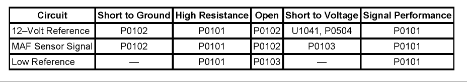
IMPORTANT:
- Always perform the Diagnostic System Check - Vehicle prior to using this diagnostic procedure. See: Diagnostic Trouble Code Tests and Associated Procedures
- If there are any other DTCs set, diagnose those first.
MAF Sensor
CIRCUIT/SYSTEM DESCRIPTION
The mass air flow (MAF) sensor is an air flow meter that measures the amount of air entering the engine. The engine control module (ECM) uses the MAF sensor voltage signal to provide the correct fuel delivery for a reduction in emissions. The ECM uses the MAF sensor signal to control fuel delivery until a calibrated amount of engine air flow is attained. The MAF sensor produces an output voltage based on the inlet air flow through the air induction system. This output voltage will display on the scan tool as a voltage parameter and as a grams per second (g/s) parameter. The ECM compares the actual MAF sensor voltage signal to a predicted MAF value. This comparison will determine if the signal is stuck, or is too low or too high for a given operating condition.
CONDITIONS FOR RUNNING THE DTC
- DTC P0102, P0103, P0106, P0107, P0108, P0112, P0113, P0117, P0118, P0642, P0643, P0652, P0698, P0699, P2228, P2229 are not set.
- The ignition 1 signal is between 9-18 volts .
- The intake air temperature (IAT) Sensor parameter is more than -20�C (-4�F) .
- The engine coolant temperature (ECT) Sensor parameter is more than -20�C (-4�F) .
- The BARO Sensor parameter is more than 71 kPa .
- The engine speed is less than 3,500 RPM .
- The engine speed is steady within a range of 50 RPM .
- The above conditions are met for more than 2 seconds
- This DTC runs continuously within the enabling conditions.
The ECM detects that the MAF sensor voltage signal is not within a predetermined range of the calculated MAF value for more than 15 seconds .
ACTION TAKEN WHEN THE DTC SETS
- The control module illuminates the malfunction indicator lamp (MIL) on the second consecutive ignition cycle that the diagnostic runs and fails.
- The control module records the operating conditions at the time the diagnostic fails. The first time the diagnostic fails, the control module stores this information in the Failure Records. If the diagnostic reports a failure on the second consecutive ignition cycle, the control module records the operating conditions at the time of the failure. The control module writes the operating conditions to the Freeze Frame and updates the Failure Records.
- The control module turns OFF the malfunction indicator lamp (MIL) after 3 consecutive ignition cycles that the diagnostic runs and does not fail.
- A current DTC, Last Test Failed, clears when the diagnostic runs and passes.
- A history DTC clears after 40 consecutive warm-up cycles, if no failures are reported by this or any other emission related diagnostic.
- Clear the MIL and the DTC with a scan tool.
- J 46091 Charge Air Cooler Tester
- J 35616-200 Test Lamp Kit
IMPORTANT: If you cannot duplicate the condition, operate the vehicle within the Conditions for Running the DTC. You may also operate the vehicle within the conditions that you observed from the Freeze Frame/Failure Records.
IMPORTANT: Verify that the engine is in good mechanical condition before continuing with this diagnostic.
Verify the integrity of the air induction system by inspecting for the following conditions:
- Restrictions in the MAF air induction system and the turbocharger system
- Restrictions in the exhaust system-Refer to Restricted Exhaust. See: Engine, Cooling and Exhaust\Exhaust System\Testing and Inspection\Symptom Related Diagnostic Procedures\Restricted Exhaust
- Leaks in the charge air cooler with a J 46091
- Leaks at the MAF/IAT sensor O-ring seal
- Leaks at the MAP pressure sensor seal
- Cracked or damaged MAF sensor housing
- Restricted intake air duct or a dirty air filter element
- Debris blocking the air sensing filaments of the MAF sensor
- A MAF sensor that is installed backwards
- An exhaust gas recirculation (EGR) valve that is stuck open.
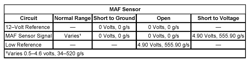
CIRCUIT/SYSTEM TESTING
IMPORTANT:
- If DTC P0405 is set, diagnose that DTC first.
- The DMM and test leads must be calibrated to 0 ohms in order to prevent misdiagnosis. Use the DMM to perform this test. Refer to the DMM User Manual for the calibration procedure.
- Use the J 35616-200 for this test. If the J 35616-200 is not available, use a test lamp that measures more than 20 ohms .
- With the ignition ON, the engine OFF, the mass air flow (MAF) sensor disconnected, connect a test lamp between the MAF sensor 12-volt reference circuit and a good ground. Measure the voltage of the MAF sensor 12-volt reference circuit at the probe end of the test lamp, with a DMM connected to a good ground.
-
- If the voltage is less than battery voltage, test the circuit for a high resistance or a faulty ECM.
- With the MAF sensor still disconnected, use the scan tool to observe the MAF Sensor parameter.
-
- If the MAF Sensor parameter is more than 0 volts , test the MAF sensor signal circuit for a short to voltage or a faulty ECM.
- Connect a jumper wire between the MAF sensor signal circuit and the IAT sensor signal circuit. Use a scan tool to observe the MAF Sensor parameter for the proper value of more than 4.7 volts and 500 g/s .
-
- If the MAF Sensor parameter is less than 4.7 volts and 500 g/s , test the MAF sensor signal circuit for a high resistance or a faulty ECM.
- Turn OFF the ignition, and all electrical accessories. Allow sufficient time for the control module to power down before taking a resistance measurement. With a DMM, measure the resistance between the low reference circuit of the MAF sensor and a good ground.
-
- If the resistance is more than 1.5 ohms , test the circuit for a high resistance or a faulty ECM.
- If the MAF sensor circuits test normal, replace the MAF sensor. Refer to Repair Instructions in this diagnostic.
IMPORTANT: Always perform the Diagnostic Repair Verification after completing the diagnostic procedure.
- Mass Air Flow (MAF)/Intake Air Temperature (IAT) Sensor Replacement for MAF/IAT sensor replacement
- Control Module References for ECM replacement, setup, and programming
Last edited by 2500HeavyDuty; 12-05-2009 at 07:40 PM.
#20
12-07-2009, 07:44 AM
Diesel Wrench
CONDITIONS FOR SETTING THE DTC
The ECM detects that the MAF sensor voltage signal is not within a predetermined range of the calculated MAF value for more than 15 seconds .
ACTION TAKEN WHEN THE DTC SETS
The control module illuminates the malfunction indicator lamp (MIL) on the second consecutive ignition cycle that the diagnostic runs and fails.
The control module records the operating conditions at the time the diagnostic fails. The first time the diagnostic fails, the control module stores this information in the Failure Records. If the diagnostic reports a failure on the second consecutive ignition cycle, the control module records the operating conditions at the time of the failure. The control module writes the operating conditions to the Freeze Frame and updates the Failure Records.
Read more: https://www.dieselbombers.com/chevy-...#ixzz0Z0flIW9h
sorry guys i wasnt trying to be an ******* but i work in the trade everyday, when i feel strong about something i follow it.
but yea i would do everything above ^. where did you find this?


