Bosch VE Pump Operation
#1
 02-04-2009, 11:13 AM


Overview
The injection pump is a single-plunger mechanical pump which meters and distributes fuel to the injectors in the correct firing order. The pump is driven by the camshaft spur belt or gear at one-half crankshaft speed. All moving parts inside the pump are lubricated by diesel fuel, so the pump is maintenance-free; diesel pumps operate reliably for a long time if clean fuel is used.
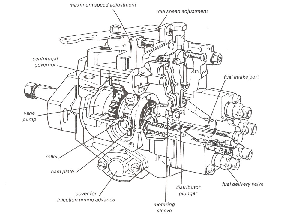
Idle speed, maximum speed, and injection timing can be adjusted with workshop equipment; the stop solenoid can be replaced, the fuel delivery valve body can be replaced, but any internal problem means replacement of the pump.
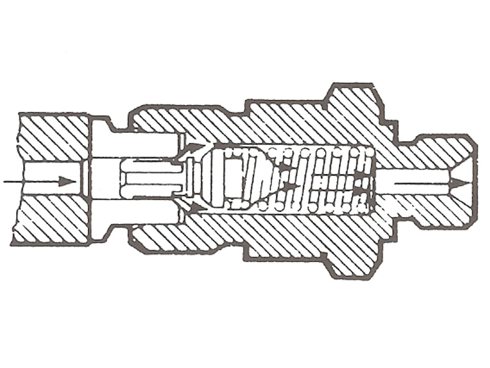
Fuel Delivery Valves
The fuel delivery valves on the injection pump help ensure that the injector will close quickly at the end of each injection. The injectors must close quickly in order to prevent fuel "dribble" which can cause pre-ignition and high exhaust emissions.
At the start of injection the delivery valve is lifted off of its seat and pressurized fuel flows to the injector:
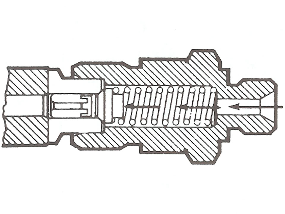
At the end of injection the delivery valve moves to the closed position. A column of fuel is now trapped in the injection line:
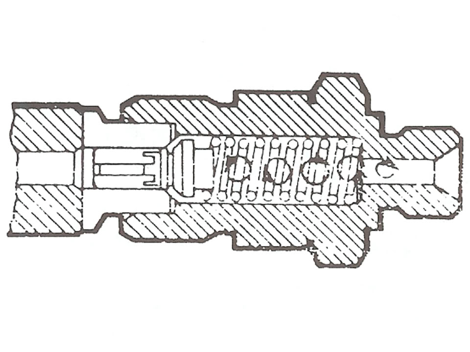
The force of the spring will push the valve back further onto its seat and the trapped column of fuel now expands. The sudden drop in pressure caused by the expanding fuel, allows the injector to snap shut and eliminate and fuel "dribble":
Vane Pump
The rotary-vane pump inside the injection pump draws fuel through the filter from the tank and supplies it to the distributor plunger.
The vane pump rotor is driven by the engine camshaft spur belt or gear. As the rotor spins, centrifugal force holds the vanes against the walls of the pressure chamber. The off-center or eccentric layout of the rotor and pressure chamber "squeezes" fuel trapped between the vanes and forces it out the delivery port.
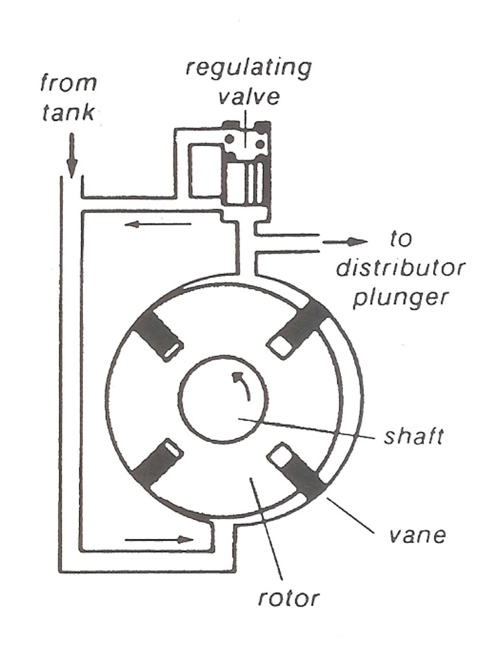
Vane pump delivery pressure is between 3-7 bar depending on the engine speed and is controlled by the regulating valve.
Vane pump fuel pressure lubricates moving parts in the rest of the pump, supplies fuel to the distributor plunger for the injectors, and controls injection timing advance mechanism.
Injection pump manufacturers use a special test "bench" to set and check internal pump pressures. The vane pump and distributor plunger injection pressures cannot be checked easily with normal workshop equipment.
If clean fuel is used, diesel injection pumps operate reliably for a long time. Diesel pumps should not be disassembled or "adjusted." Normal shop work consists only of troubleshooting to determine whether a pump might need replacement.
Injection & Distribution
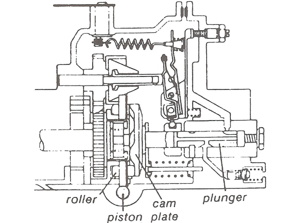
The injection pump driveshaft turns the vane pump, distributor plunger, and cam plate as a unit.
Springs hold the cam plate and distributor plunger against stationary rollers - in this way, the plunger also moves back and forth as it turns:
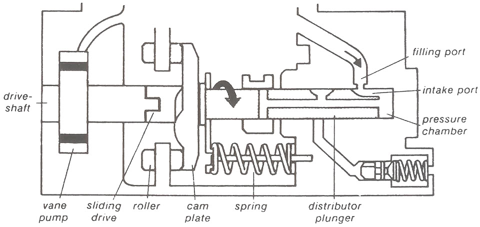
Whenever an intake port in the plunger is in line with the filling port in the pump body, fuel from the vane pump fills the pressure chamber.
As the plunger turns, the intake port is covered up so that fuel is trapped in the pressure chamber. Now, the cam plate and rollers push the plunger and pressurize the fuel to about 1800 psi.:
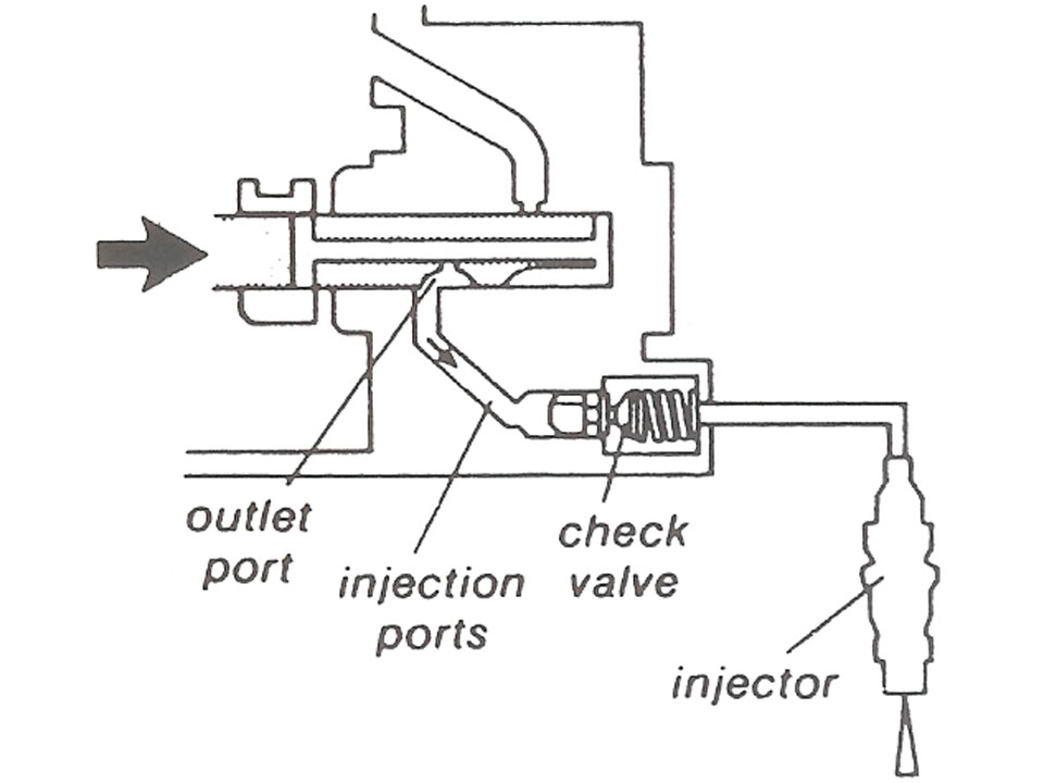
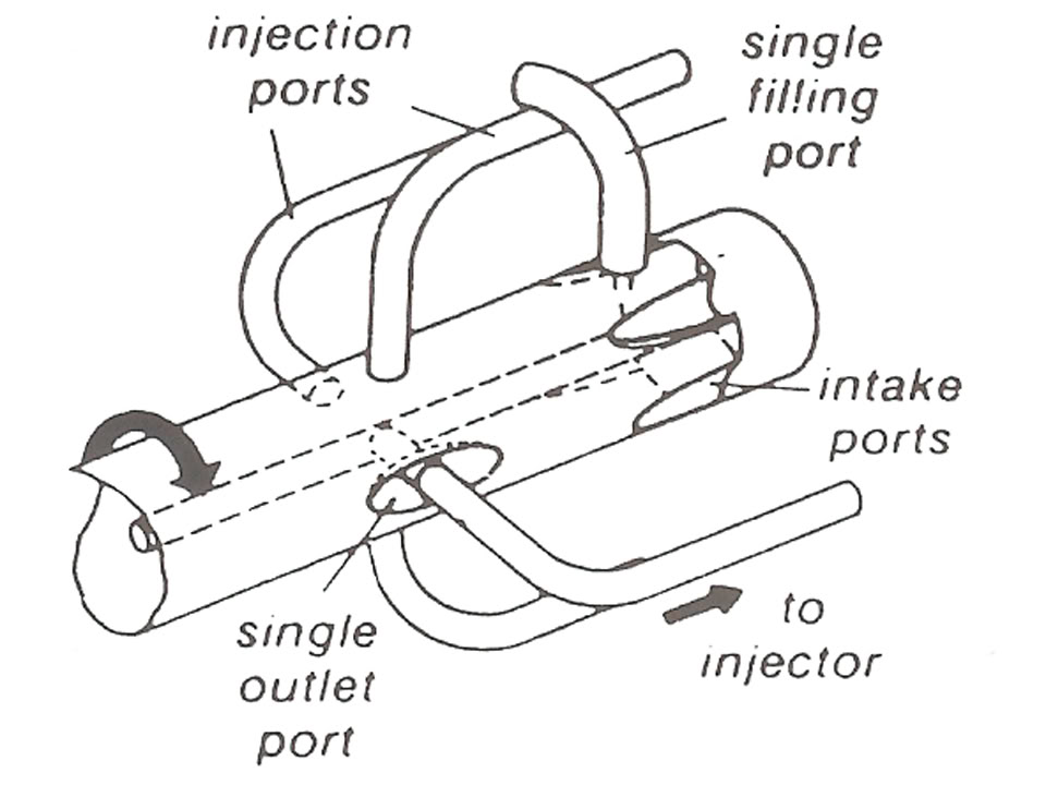
As the plunger continues to turn, the outlet port in the plunger lines up with the injection passage in the pump body, opening the check valve and supplying high-pressure fuel to the injector.
The injection ports in the pump are arranged so the injectors receive fuel in the cylinder firing sequence:
Metering Fuel
The amount of fuel injected is controlled by changing the injection cut-off point according to engine speed and load conditions.
The injection cut-off point is controlled by the position of a metering sleeve on the distributor plunger. The metering sleeve usually covers a relief port in the plunger. Uncovering the relief port stops injection.
The position of the metering sleeve is controlled by a linkage connected to a centrifugal governor and also the accelerator pedal.
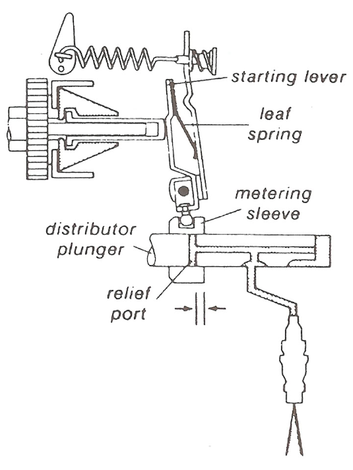
Metering Fuel - Starting
When the engine is not running, the leaf spring presses the starting lever to the left so that the metering sleeve moves to the right.
The distributor plunger must move further before the relief port is exposed. Injection lasts longer so that more fuel is supplied during starting:
The injection pump is a single-plunger mechanical pump which meters and distributes fuel to the injectors in the correct firing order. The pump is driven by the camshaft spur belt or gear at one-half crankshaft speed. All moving parts inside the pump are lubricated by diesel fuel, so the pump is maintenance-free; diesel pumps operate reliably for a long time if clean fuel is used.
Idle speed, maximum speed, and injection timing can be adjusted with workshop equipment; the stop solenoid can be replaced, the fuel delivery valve body can be replaced, but any internal problem means replacement of the pump.
Fuel Delivery Valves
The fuel delivery valves on the injection pump help ensure that the injector will close quickly at the end of each injection. The injectors must close quickly in order to prevent fuel "dribble" which can cause pre-ignition and high exhaust emissions.
At the start of injection the delivery valve is lifted off of its seat and pressurized fuel flows to the injector:
At the end of injection the delivery valve moves to the closed position. A column of fuel is now trapped in the injection line:
The force of the spring will push the valve back further onto its seat and the trapped column of fuel now expands. The sudden drop in pressure caused by the expanding fuel, allows the injector to snap shut and eliminate and fuel "dribble":
Vane Pump
The rotary-vane pump inside the injection pump draws fuel through the filter from the tank and supplies it to the distributor plunger.
The vane pump rotor is driven by the engine camshaft spur belt or gear. As the rotor spins, centrifugal force holds the vanes against the walls of the pressure chamber. The off-center or eccentric layout of the rotor and pressure chamber "squeezes" fuel trapped between the vanes and forces it out the delivery port.
Vane pump delivery pressure is between 3-7 bar depending on the engine speed and is controlled by the regulating valve.
Vane pump fuel pressure lubricates moving parts in the rest of the pump, supplies fuel to the distributor plunger for the injectors, and controls injection timing advance mechanism.
Injection pump manufacturers use a special test "bench" to set and check internal pump pressures. The vane pump and distributor plunger injection pressures cannot be checked easily with normal workshop equipment.
If clean fuel is used, diesel injection pumps operate reliably for a long time. Diesel pumps should not be disassembled or "adjusted." Normal shop work consists only of troubleshooting to determine whether a pump might need replacement.
Injection & Distribution
The injection pump driveshaft turns the vane pump, distributor plunger, and cam plate as a unit.
Springs hold the cam plate and distributor plunger against stationary rollers - in this way, the plunger also moves back and forth as it turns:
Whenever an intake port in the plunger is in line with the filling port in the pump body, fuel from the vane pump fills the pressure chamber.
As the plunger turns, the intake port is covered up so that fuel is trapped in the pressure chamber. Now, the cam plate and rollers push the plunger and pressurize the fuel to about 1800 psi.:
As the plunger continues to turn, the outlet port in the plunger lines up with the injection passage in the pump body, opening the check valve and supplying high-pressure fuel to the injector.
The injection ports in the pump are arranged so the injectors receive fuel in the cylinder firing sequence:
Metering Fuel
The amount of fuel injected is controlled by changing the injection cut-off point according to engine speed and load conditions.
The injection cut-off point is controlled by the position of a metering sleeve on the distributor plunger. The metering sleeve usually covers a relief port in the plunger. Uncovering the relief port stops injection.
The position of the metering sleeve is controlled by a linkage connected to a centrifugal governor and also the accelerator pedal.
Metering Fuel - Starting
When the engine is not running, the leaf spring presses the starting lever to the left so that the metering sleeve moves to the right.
The distributor plunger must move further before the relief port is exposed. Injection lasts longer so that more fuel is supplied during starting:
#2
02-04-2009, 11:15 AM
Metering Fuel - Idle
At idle speed, the weights in the centrifugal governor are partly expanded so that governor sleeve move to the right. The starting lever is pushed against the control lever so that the metering sleeve moves to the left.
The distributor plunger now moves a shorts distance before the relief port is uncovered. Injection lasts a short time fo that a small amount of fuel is supplied at idle:
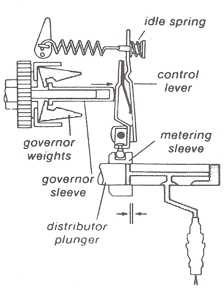
The injection pump automatically compensates for effects of temperature and load changes at idle. When idle speed begins to drop, the centrifugal governor weights and the governor sleeve retract; the idle spring then pushes the metering sleeve to the right, increasing the amount of fuel to correct the idle speed.
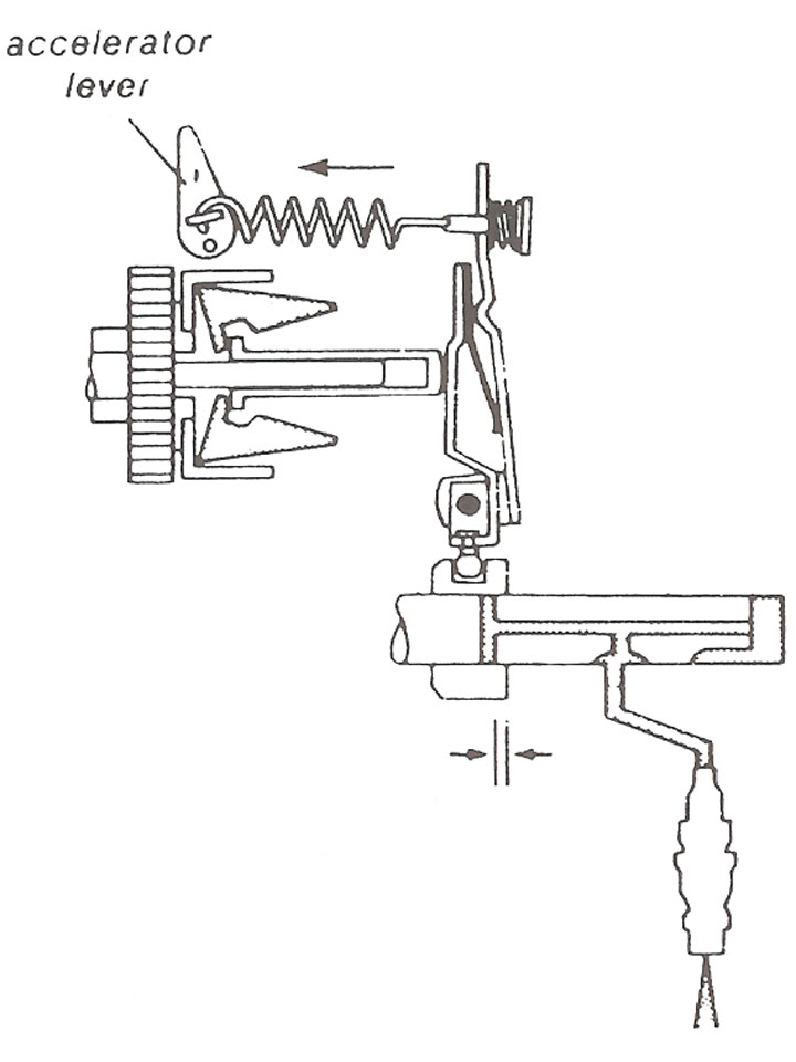
Metering Fuel - Acceleration
During acceleration, the control lever is pulled to the left by the linkage from the accelerator pedal.
The metering sleeve is moved to the right so that more fuel is injected before the relief port in uncovered. Engine speed increases until the movemnt of the governor "neutralizes" the effect of the pedal linkage:
Metering Fuel - Maximum Speed
With the pedal linkage at "full load," engine speed increases to about 5400 rpm. At this point, the governor is spinning with enough centrifugal force for the governor sleeve to "stretch" the governor spring and force the control lever to the right.
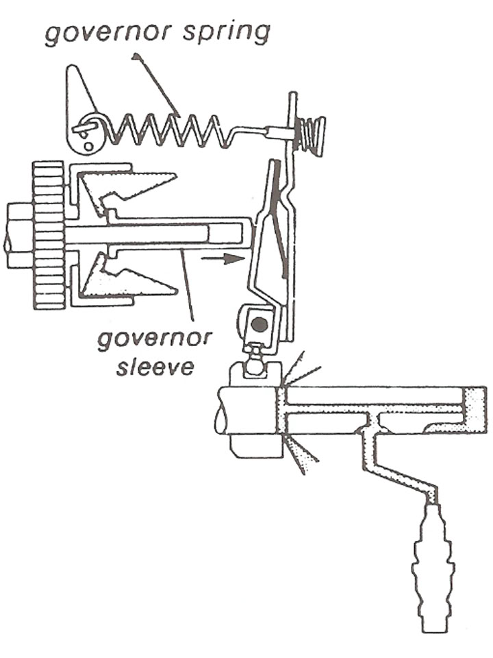
The metering sleeve moves far enough to the left to uncover the relief port at the beginning of the distributor plunger stroke. There is no pressure for injection until engine speed drops and the metering sleeve moves to the right again.
This provision acts as a speed limiter and is designed to react slowly enough so that engine performance simply "flattens out" at the top limit.
Injection Timing Advance
Near the end of each compression stroke, diesel fuel is injected directly into the combustion chamber. Injection must continue well past piston TDC in order to burn the necessary amount of fuel to provide engine power.
As engine speed increases, stroke timing becomes shorter and injection timing becomes longer. Burning must begin sooner to ensure that peak combustion pressures still occur at the most efficient point after TDC.
Diesel injection timing is advanced by a hydraulic piston in the injection pump:
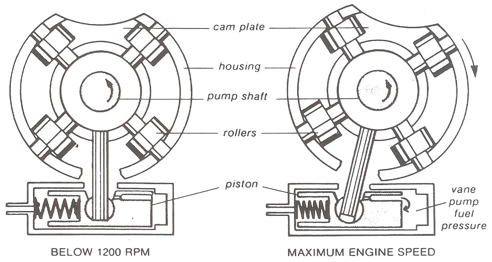
As engine speed increases, fuel pressure from the vane pump also increases. Vane pump pressure pushes the injection advance piston to the left against the spring so that the roller housing turns slightly.
Since the cam plate is turning in the opposite direction, the "ramps" on the cam plate engage the roller sooner whenever the injection advance piston moves to the left. This means that the distributor plunger beings injection sooner.
The injection timing advance piston is located in the bottom of the injection pump body:
The only cold start and warm-up device necessary for the diesel fuel system is a control which advances injection timing at idle and during low speed running.
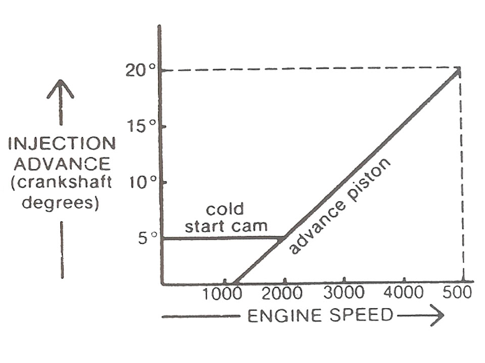
A lever turns a cam which pushes the hydraulic piston to the left. This advances injection time about 5 degrees.
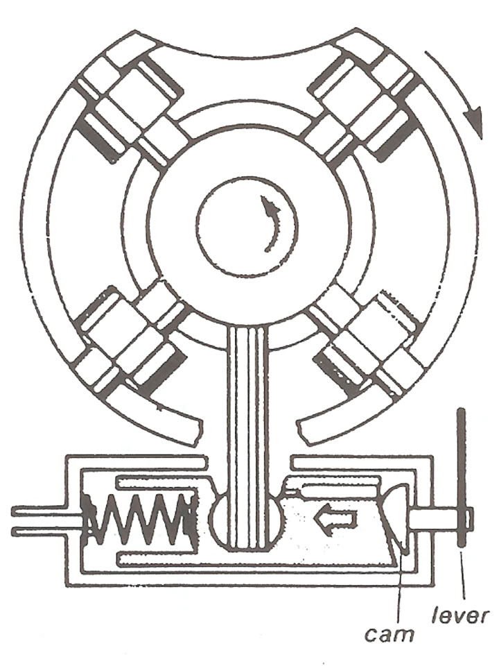
This injection advance provides more time for the fuel to burn, which improves performance and prevents smoking during cold starts and warm-up.
The cold start cam does not advance the complete range of injection timing. Above 2200 rpm, the piston operates normally and does not contact the cam:
Injection Timing
Since diesel fuel ignites in the hot compressed air as soon as injection begins, injection timing is as important as gasoline engine spark timing.
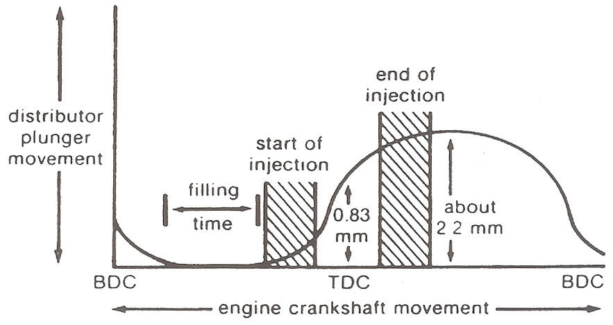
The actual moment of injection cannot be checked easily because it is affected not only by the injection advance mechanism but also by the exact opening pressure of each injector.
Thanks To Jimbo486 @ DTR for this!
At idle speed, the weights in the centrifugal governor are partly expanded so that governor sleeve move to the right. The starting lever is pushed against the control lever so that the metering sleeve moves to the left.
The distributor plunger now moves a shorts distance before the relief port is uncovered. Injection lasts a short time fo that a small amount of fuel is supplied at idle:
The injection pump automatically compensates for effects of temperature and load changes at idle. When idle speed begins to drop, the centrifugal governor weights and the governor sleeve retract; the idle spring then pushes the metering sleeve to the right, increasing the amount of fuel to correct the idle speed.
Metering Fuel - Acceleration
During acceleration, the control lever is pulled to the left by the linkage from the accelerator pedal.
The metering sleeve is moved to the right so that more fuel is injected before the relief port in uncovered. Engine speed increases until the movemnt of the governor "neutralizes" the effect of the pedal linkage:
Metering Fuel - Maximum Speed
With the pedal linkage at "full load," engine speed increases to about 5400 rpm. At this point, the governor is spinning with enough centrifugal force for the governor sleeve to "stretch" the governor spring and force the control lever to the right.
The metering sleeve moves far enough to the left to uncover the relief port at the beginning of the distributor plunger stroke. There is no pressure for injection until engine speed drops and the metering sleeve moves to the right again.
This provision acts as a speed limiter and is designed to react slowly enough so that engine performance simply "flattens out" at the top limit.
Injection Timing Advance
Near the end of each compression stroke, diesel fuel is injected directly into the combustion chamber. Injection must continue well past piston TDC in order to burn the necessary amount of fuel to provide engine power.
As engine speed increases, stroke timing becomes shorter and injection timing becomes longer. Burning must begin sooner to ensure that peak combustion pressures still occur at the most efficient point after TDC.
Diesel injection timing is advanced by a hydraulic piston in the injection pump:
As engine speed increases, fuel pressure from the vane pump also increases. Vane pump pressure pushes the injection advance piston to the left against the spring so that the roller housing turns slightly.
Since the cam plate is turning in the opposite direction, the "ramps" on the cam plate engage the roller sooner whenever the injection advance piston moves to the left. This means that the distributor plunger beings injection sooner.
The injection timing advance piston is located in the bottom of the injection pump body:
The only cold start and warm-up device necessary for the diesel fuel system is a control which advances injection timing at idle and during low speed running.
A lever turns a cam which pushes the hydraulic piston to the left. This advances injection time about 5 degrees.
This injection advance provides more time for the fuel to burn, which improves performance and prevents smoking during cold starts and warm-up.
The cold start cam does not advance the complete range of injection timing. Above 2200 rpm, the piston operates normally and does not contact the cam:
Injection Timing
Since diesel fuel ignites in the hot compressed air as soon as injection begins, injection timing is as important as gasoline engine spark timing.
The actual moment of injection cannot be checked easily because it is affected not only by the injection advance mechanism but also by the exact opening pressure of each injector.
Thanks To Jimbo486 @ DTR for this!
The following 4 users liked this post by RSWORDS:
#3
02-08-2009, 06:30 PM
Diesel Bomber

#4
02-08-2009, 06:46 PM


#7
01-20-2010, 12:43 PM
i think i deserve to be given credit when credit is due. i spent a decent amount of time scanning all those images and typing everything from my fuel injection handbook when i studied and became certified in diesel technology. i think someone forgot to give credit when this was posted here. here's where the write-up originates and where every member would tell you that i wrote it. should be pretty obvious too....
http://www.dieseltruckresource.com/d....html?t=231914
you're welcome
http://www.dieseltruckresource.com/d....html?t=231914
you're welcome
The following 3 users liked this post by jimbo486:

#9
01-20-2010, 05:07 PM
Diesel Fan
Join Date: Nov 2009
Location: Mountain Home, Idaho
Posts: 45
Likes: 0
Received 0 Likes
on
0 Posts
#10
01-20-2010, 05:20 PM
Diesel Fan
Under "Metering fuel-Maximum speed" is the"5400 RPM" a typo?
---AutoMerged DoublePost---
Thank you!
---AutoMerged DoublePost---
i think i deserve to be given credit when credit is due. i spent a decent amount of time scanning all those images and typing everything from my fuel injection handbook when i studied and became certified in diesel technology. i think someone forgot to give credit when this was posted here. here's where the write-up originates and where every member would tell you that i wrote it. should be pretty obvious too....
http://www.dieseltruckresource.com/d....html?t=231914
you're welcome
http://www.dieseltruckresource.com/d....html?t=231914
you're welcome
Last edited by 440warwagon; 01-20-2010 at 05:20 PM. Reason: Automerged Doublepost


