Bosch VE Pump Operation
#11
 01-20-2010, 09:24 PM


 to whoever posted it and to the guy that wrote it
#13
03-18-2010, 07:11 PM

Very good, useful and complete description, for us all, to better understand how that pump works. Tks.
One question: I have one of these pumps for my 6 cilinders naturally aspirated engine.
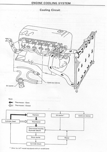
In the oil & water refrigerator circuit there is a device called "cold start device" which function is to improve performance of the engine at low rpm and at start.
In my engine, a RD28 Nissan, there is a water circuit that cross that device, I suppose to warm it up or to activate it when the engine is just starting, when it is cold.
For reasons I don+t know, they sold me the engine with that device shunted, I mean, water does not circulate for the cold start device and goes directly to the oil cooler device.
This may be affecting the engine performance at low rpm's according to yr article. Am I right?
I want to connect that circuit, but don�t know the circulation direction. Maybe it is not relevant? What do you think?
The cold start assembly is instaled in the VE Bosch pump.
If you are familiar with this kind of engine may answer my question right away. But if not, I may scan the circuit images and send them to you.
This engine is a 6 in line, 2.8 liters.
Thank you in advance,
OldBeaver
(New to the forum, this is my first post)
One question: I have one of these pumps for my 6 cilinders naturally aspirated engine.
In the oil & water refrigerator circuit there is a device called "cold start device" which function is to improve performance of the engine at low rpm and at start.
In my engine, a RD28 Nissan, there is a water circuit that cross that device, I suppose to warm it up or to activate it when the engine is just starting, when it is cold.
For reasons I don+t know, they sold me the engine with that device shunted, I mean, water does not circulate for the cold start device and goes directly to the oil cooler device.
This may be affecting the engine performance at low rpm's according to yr article. Am I right?
I want to connect that circuit, but don�t know the circulation direction. Maybe it is not relevant? What do you think?
The cold start assembly is instaled in the VE Bosch pump.
If you are familiar with this kind of engine may answer my question right away. But if not, I may scan the circuit images and send them to you.
This engine is a 6 in line, 2.8 liters.
Thank you in advance,
OldBeaver
(New to the forum, this is my first post)
Metering Fuel - Idle
At idle speed, the weights in the centrifugal governor are partly expanded so that governor sleeve move to the right. The starting lever is pushed against the control lever so that the metering sleeve moves to the left.
The distributor plunger now moves a shorts distance before the relief port is uncovered. Injection lasts a short time fo that a small amount of fuel is supplied at idle:
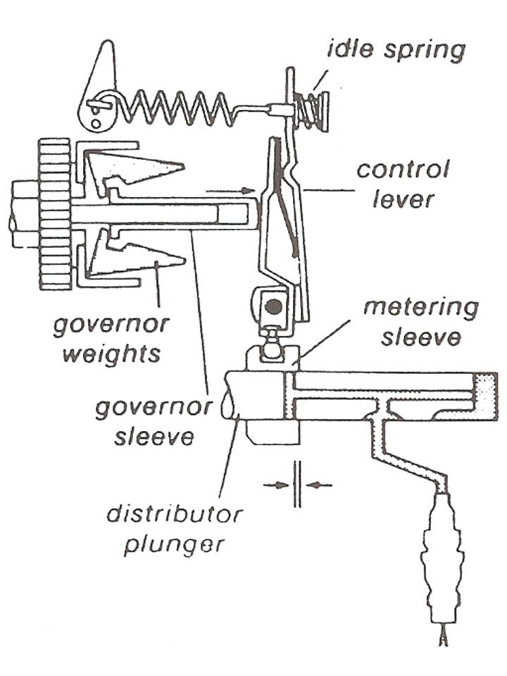
The injection pump automatically compensates for effects of temperature and load changes at idle. When idle speed begins to drop, the centrifugal governor weights and the governor sleeve retract; the idle spring then pushes the metering sleeve to the right, increasing the amount of fuel to correct the idle speed.
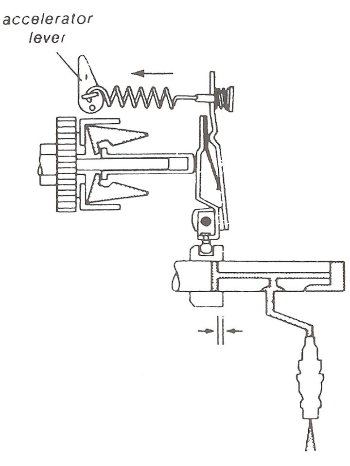
Metering Fuel - Acceleration
During acceleration, the control lever is pulled to the left by the linkage from the accelerator pedal.
The metering sleeve is moved to the right so that more fuel is injected before the relief port in uncovered. Engine speed increases until the movemnt of the governor "neutralizes" the effect of the pedal linkage:
Metering Fuel - Maximum Speed
With the pedal linkage at "full load," engine speed increases to about 5400 rpm. At this point, the governor is spinning with enough centrifugal force for the governor sleeve to "stretch" the governor spring and force the control lever to the right.
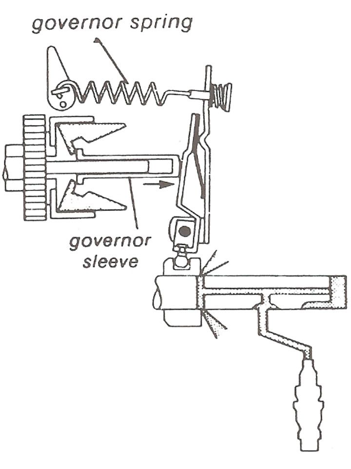
The metering sleeve moves far enough to the left to uncover the relief port at the beginning of the distributor plunger stroke. There is no pressure for injection until engine speed drops and the metering sleeve moves to the right again.
This provision acts as a speed limiter and is designed to react slowly enough so that engine performance simply "flattens out" at the top limit.
Injection Timing Advance
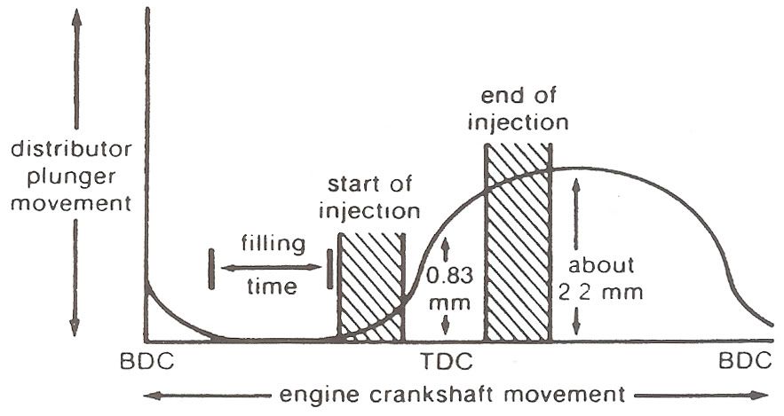
Near the end of each compression stroke, diesel fuel is injected directly into the combustion chamber. Injection must continue well past piston TDC in order to burn the necessary amount of fuel to provide engine power.
As engine speed increases, stroke timing becomes shorter and injection timing becomes longer. Burning must begin sooner to ensure that peak combustion pressures still occur at the most efficient point after TDC.
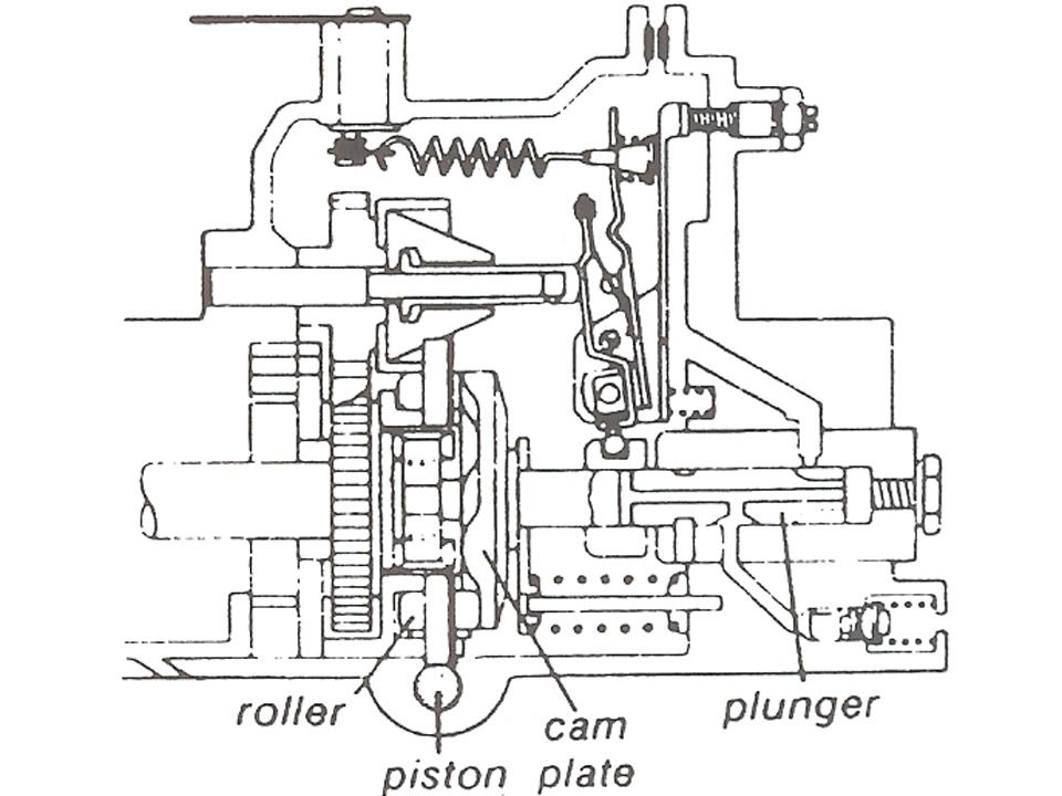
Diesel injection timing is advanced by a hydraulic piston in the injection pump:
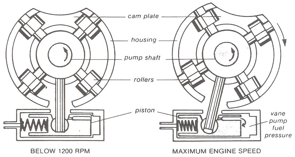
As engine speed increases, fuel pressure from the vane pump also increases. Vane pump pressure pushes the injection advance piston to the left against the spring so that the roller housing turns slightly.
Since the cam plate is turning in the opposite direction, the "ramps" on the cam plate engage the roller sooner whenever the injection advance piston moves to the left. This means that the distributor plunger beings injection sooner.
The injection timing advance piston is located in the bottom of the injection pump body:
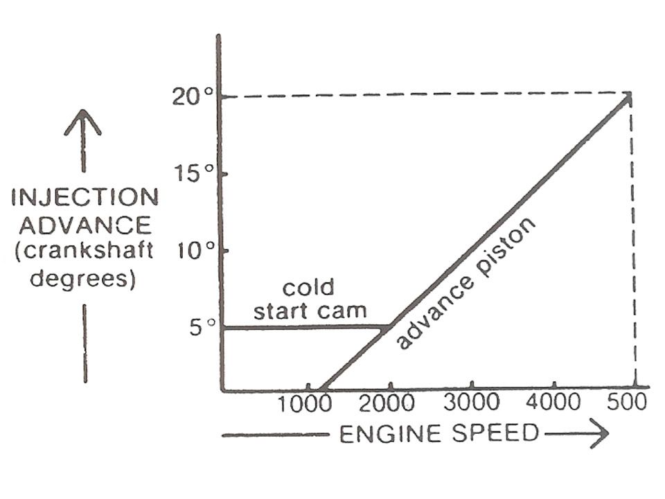
The only cold start and warm-up device necessary for the diesel fuel system is a control which advances injection timing at idle and during low speed running.
A lever turns a cam which pushes the hydraulic piston to the left. This advances injection time about 5 degrees.

This injection advance provides more time for the fuel to burn, which improves performance and prevents smoking during cold starts and warm-up.
The cold start cam does not advance the complete range of injection timing. Above 2200 rpm, the piston operates normally and does not contact the cam:
Injection Timing
Since diesel fuel ignites in the hot compressed air as soon as injection begins, injection timing is as important as gasoline engine spark timing.
The actual moment of injection cannot be checked easily because it is affected not only by the injection advance mechanism but also by the exact opening pressure of each injector.
Thanks To Jimbo486 @ DTR for this!
At idle speed, the weights in the centrifugal governor are partly expanded so that governor sleeve move to the right. The starting lever is pushed against the control lever so that the metering sleeve moves to the left.
The distributor plunger now moves a shorts distance before the relief port is uncovered. Injection lasts a short time fo that a small amount of fuel is supplied at idle:
The injection pump automatically compensates for effects of temperature and load changes at idle. When idle speed begins to drop, the centrifugal governor weights and the governor sleeve retract; the idle spring then pushes the metering sleeve to the right, increasing the amount of fuel to correct the idle speed.
Metering Fuel - Acceleration
During acceleration, the control lever is pulled to the left by the linkage from the accelerator pedal.
The metering sleeve is moved to the right so that more fuel is injected before the relief port in uncovered. Engine speed increases until the movemnt of the governor "neutralizes" the effect of the pedal linkage:
Metering Fuel - Maximum Speed
With the pedal linkage at "full load," engine speed increases to about 5400 rpm. At this point, the governor is spinning with enough centrifugal force for the governor sleeve to "stretch" the governor spring and force the control lever to the right.
The metering sleeve moves far enough to the left to uncover the relief port at the beginning of the distributor plunger stroke. There is no pressure for injection until engine speed drops and the metering sleeve moves to the right again.
This provision acts as a speed limiter and is designed to react slowly enough so that engine performance simply "flattens out" at the top limit.
Injection Timing Advance
Near the end of each compression stroke, diesel fuel is injected directly into the combustion chamber. Injection must continue well past piston TDC in order to burn the necessary amount of fuel to provide engine power.
As engine speed increases, stroke timing becomes shorter and injection timing becomes longer. Burning must begin sooner to ensure that peak combustion pressures still occur at the most efficient point after TDC.
Diesel injection timing is advanced by a hydraulic piston in the injection pump:
As engine speed increases, fuel pressure from the vane pump also increases. Vane pump pressure pushes the injection advance piston to the left against the spring so that the roller housing turns slightly.
Since the cam plate is turning in the opposite direction, the "ramps" on the cam plate engage the roller sooner whenever the injection advance piston moves to the left. This means that the distributor plunger beings injection sooner.
The injection timing advance piston is located in the bottom of the injection pump body:
The only cold start and warm-up device necessary for the diesel fuel system is a control which advances injection timing at idle and during low speed running.
A lever turns a cam which pushes the hydraulic piston to the left. This advances injection time about 5 degrees.
This injection advance provides more time for the fuel to burn, which improves performance and prevents smoking during cold starts and warm-up.
The cold start cam does not advance the complete range of injection timing. Above 2200 rpm, the piston operates normally and does not contact the cam:
Injection Timing
Since diesel fuel ignites in the hot compressed air as soon as injection begins, injection timing is as important as gasoline engine spark timing.
The actual moment of injection cannot be checked easily because it is affected not only by the injection advance mechanism but also by the exact opening pressure of each injector.
Thanks To Jimbo486 @ DTR for this!
#14
03-18-2010, 07:33 PM

#15
03-19-2010, 06:32 AM

Diesel Bombers Sponsor
#16
03-19-2010, 07:11 AM

@cummins guy:
That was (and still used) method to preheat the chamber.
This is a cold start aid and different from the KSB.( more like the glow plugs and grid heater)
There are several ways possible to gain advance during cold start :
- the electric KSB (as desrcibed above)
- the manual (old fashioned) KSB with a wire that actuates a lever to adjust advance and idle speed (typical in VW engines from 86 to 92)
- the automatic wax expansion chamber which adjusts advance acording to coolant temperature using the expanding wax chamber to adjust a lever and advance.
all methods interfere at the same point and act in the same way.
@Oldbeaver:
Direction of the flow should be directed from the hot engine through the wax chamber.
It's a device typically seen in the beginning of the 90's.
It's interesting to hear that the RD 28 (Nissan Patrol)has a VP pump. Over here in europe this engine has a Denso license built Bosch inline pump.
That was (and still used) method to preheat the chamber.
This is a cold start aid and different from the KSB.( more like the glow plugs and grid heater)
There are several ways possible to gain advance during cold start :
- the electric KSB (as desrcibed above)
- the manual (old fashioned) KSB with a wire that actuates a lever to adjust advance and idle speed (typical in VW engines from 86 to 92)
- the automatic wax expansion chamber which adjusts advance acording to coolant temperature using the expanding wax chamber to adjust a lever and advance.
all methods interfere at the same point and act in the same way.
@Oldbeaver:
Direction of the flow should be directed from the hot engine through the wax chamber.
It's a device typically seen in the beginning of the 90's.
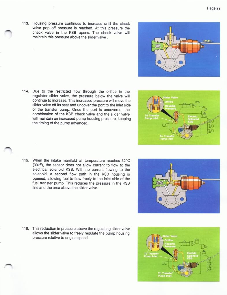
It's interesting to hear that the RD 28 (Nissan Patrol)has a VP pump. Over here in europe this engine has a Denso license built Bosch inline pump.
Last edited by Deezel Stink3r; 03-19-2010 at 07:15 AM.
#17
03-19-2010, 03:48 PM
Dear Beagle1,
I am trying to attach pictures of the circuits of the cold start device from the manual, as well as a picture of the device itself.
Hope I can paste them here.
I couldn't.
Will upload them to a site.
Old Beaver
---AutoMerged DoublePost---
Here are some pictures to show how this device is located in the RD28 diesel engine:
http://www.flickr.com/photos/oldbeaver/4446411674/
This is the cold start device:
and these are the complementary pictures.
Forgive me for not being able to arrange the pictures as well as Beagle1 !
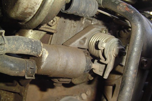
From the pictures, It seems that the cold start device has an actuator to make some change in the injection process. But I cannot say what is the action the cold start device makes. At present, it is not connected, I mean, water is not circulating through it.
What do you think?
Old Beaver
I am trying to attach pictures of the circuits of the cold start device from the manual, as well as a picture of the device itself.
Hope I can paste them here.
I couldn't.
Will upload them to a site.
Old Beaver
---AutoMerged DoublePost---
Here are some pictures to show how this device is located in the RD28 diesel engine:
http://www.flickr.com/photos/oldbeaver/4446411674/
This is the cold start device:
and these are the complementary pictures.
Forgive me for not being able to arrange the pictures as well as Beagle1 !
From the pictures, It seems that the cold start device has an actuator to make some change in the injection process. But I cannot say what is the action the cold start device makes. At present, it is not connected, I mean, water is not circulating through it.
What do you think?
Old Beaver
Last edited by RSWORDS; 03-19-2010 at 06:34 PM. Reason: FIXED PICS
#19
03-21-2010, 07:04 PM


